

Introduction: Simple TACS for Analogue Electromancers


DISCLAIMER: MAN, IT GETS BORING WRITING DISCLAIMERS AT THE BEGINNING OF NEARLY EVERY INSTRUCTABLE I PUBLISH. THIS DEVICE OPERATES BY RUNNING A CURRENT THROUGH THE HUMAN BRAIN. ELECTROCUTION IS NOT TECHNICALLY A RISK, BUT ONLY BECAUSE THE NORMAL OPERATION MODE OF THIS DEVICE GUARANTEES IT (<3.6mA). THIS DEVICE CAN CAUSE PERMANENT BRAIN DAMAGE, SEIZURES, STROKES, HEMORRHAGE, DISMEMBERMENT, IMMOLATION, DEATH, OR ANY OF THE ABOVE IN ANY COMBINATION, IN ADDITION TO THE RISKS NOT SPECIFICALLY LISTED HERE.
I've been working on tACS hardware since January 2014, and I've built five different iterations of the hardware so far. Out of all of them, this tACS design is the simplest to build and operate. It is not capable of operating at frequencies >30Hz (assuming your screen refreshes at 60Hz), like my other published design is, but you won't have to mess around with line voltage, firmware, surface-mount soldering, and custom drivers to use it. The arc I unintentionally pulled off the 108V battery bank with my soldering iron during assembly strongly implies that caution is advisable. You can use a voltage quadrupler after a 24VAC transformer if you want to run this device from line power.
These are instructions for building a computer-controlled tACS device. Transcranial alternating current stimulation (tACS) is a form of neuronal stimulation that operates by running an alternating current through the human brain. This current can be any waveform from random noise (tRNS is the official research term if you want to be fancy about it) to a clean sine wave. There is some evidence that the brain's own oscillation pattern will synchronize with externally applied alternating current(1), and specific cortical oscillation patterns may be associated with specific thought processes(2). Since EEGs directly record cortical oscillation patterns, it seems reasonable to hypothesize that these recorded patterns could be superimposed on a second brain using tACS in order to affect mental processing, and perhaps even to induce mental synchrony. The hardware described here has been developed for an experiment being assembled to begin preliminary testing of this hypothesis.
This is a backbone technology for the formation of the collective of superhuman cyborgs necessary to save the world. The development of this technology and others like it seems practically inevitable at this point. It is preferable that technologies such as this one, that could so profoundly influence humanity, be developed and implemented in an open manner -- under the watchful guidance of the public at large -- rather than secretly, by military or intelligence agencies.
Citations
(1) Transcranial alternating current stimulation (tACS), Walter Paulus et al., Frontiers in human neuroscience, http://www.ncbi.nlm.nih.gov/pmc/articles/PMC36953...
(2) Spectral fingerprints of large-scale neuronal interactions, Markus Siegel at al., Nature reviews neuroscience, http://www.nature.com/nrn/journal/v13/n2/full/nrn...
Step 1: System Specifications

This device controls an output current through a human brain based on the brightness of a computer screen. It is nearly identical to the voltage-to-current converter submodule of my previous tACS device design. I have added the minimum number of components required to make it a working tACS device.
[ NORMAL OPERATING PARAMETERS ]
Output current when properly calibrated (output zeroed at R=G=B=127 on your screen):
R=G=B=102: Iout = -2mA
R=G=B=127: Iout = 0mA
R=G=B=160: Iout = 2mA
Minimum output current (open-circuit photoresistor): -3.6mA
Maximum output current (short-circuit photoresistor): 3.1mA
Maximum load resistance to maintain accurate current control: 9000 Ohms
Minimum load resistance to maintain accurate current control: 0 Ohms
[ FAULT CONDITION OPERATING PARAMETERS ]
Primary regulator failure (Vsupply = +/- 60V): -7mA < Iout < 5mA
Primary and secondary regulator failure (Vsupply = +/- 60V): -9mA < Iout < 9mA
Primary and secondary regulator failure and worst-case wiring error and worst-case fault condition (Vsupply wired directly to 240VAC mains, perfectly conductive user grasping water pipe, unit immersed in conductive fluid): -52mA < Iout < 52mA
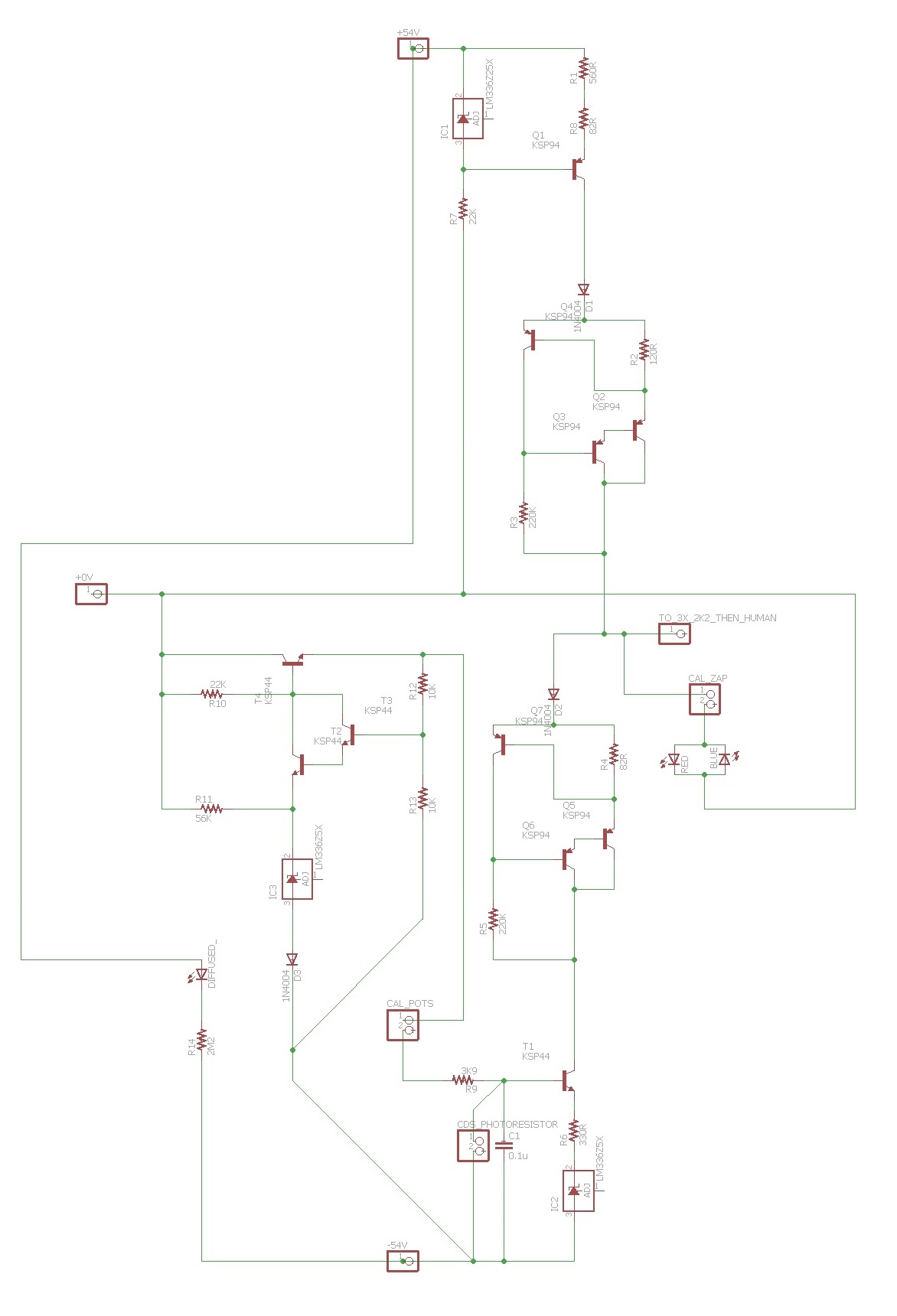
Step 2: System Schematic


Instructables compressed that second schematic to the point that it's barely legible, so I've put a clearly legible version of the schematic up on my website.
Those three 2K2 resistors in series with the output must be mounted off the circuit board, heatshrunk inline with the output lead! Perform testing of the secondary current regulators before using this device. To test the secondary regulators, first short Q1's collector and emitter, disconnect -54V, and verify that Iout < 5mA +/- 20%. Then, short T1's collector and emitter, disconnect +54V, and verify that Iout > -7mA +/- 20%.
To calibrate: Attach photoresistor to computer screen, set R=G=B=127. Set ZAP_CAL switch to closed position. Adjust coarse potentiometer to around the point where red (Iout > 0) and blue (Iout < 0) calibration LEDs trade off. Adjust fine potentiometer to make red and blue LEDs the same brightness, ideally both off, but electrical noise may cause both to glow faintly.
Step 3: The Board Files
For those of you with EAGLE (it's free, from CADSoft, for the "light" edition), TM02.zip contains the schematic and board files of this device. Want to order boards? I've included Gerber files, prepped for SeeedStudio's PCB fab service. You'll have to select the "5cm x 10cm" board size after uploading OPTOTACS_GERB.zip but all other options can be left at default.


