

Introduction: Simplified Electric Imp to Arduino Due Tutorial


Introduction:
This is a basic tutorial to send information from the Electric Imp to the Arduino Due through UART (RX, TX) I am pretty new to both so some things I write may be incorrect. Most of the information I got from
https://www.sparkfun.com/tutorials/397
If you know how to program well that tutorial may be way better then this one, but I thought this would be a more basic and easier tutorial for people to use.
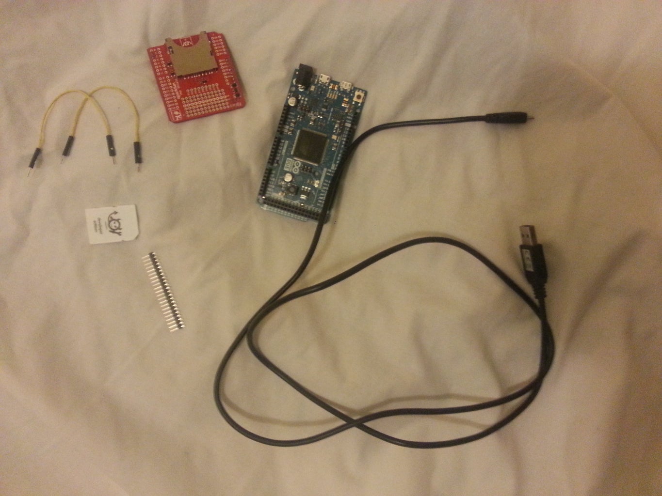
Things You Need:
Electric Imp Shield
Commissioned Electric Imp (http://devwiki.electricimp.com/doku.php?id=commissioning)
Electric Imp Account
Arduino Due
1 USB to Arduino Cable
2 Wires
2 Headers
Step 1: Connect Everything Up


First you have to solder the headers into the electric imp shield, to power it you need to have 5V and GND connected from the Arduino Due to the Electric Imp Shield so these are really the only ones you have to solder but its better to do at least a row as you can see in the pictures.
You then need to place the Electric Imp card into the shield. I'm Assuming if everything is commissioned already this part is probably all already done.
Step 2: Actually Connecting the Arduino Due With the Electric Imp

Since this is the Arduino Due, you unfortunately can't use software serial library as far as I am aware, due to this you have to use the hardware serials on the Arduino and the Software on the electric imp.
It's important to look at the schematic of the Arduino Shield for the imp
http://dlnmh9ip6v2uc.cloudfront.net/datasheets/Dev/Arduino/Shields/electric-imp-shield-v11.pdf
Hosted by SparkFun https://www.sparkfun.com/products/11401
On here you can see that for the UART the RX and TX for software is on holes 8 and 9 of the arduino shield.
8->Tx
9->Rx
So we will connect a cable from each of this to the hardware UART Rx and Tx of the Arduino Due. I use RX1 (input 18) and Tx1 (input 19) but note that the Rx of the Imp Shield connects to the Tx of the Arduino Due, and the Tx of the imp shield connects to the Rx of the Arudino Due.
That way you can transfer with the shield and read with the arduino, or read with the shield and transfer with the arduino.
Step 3: Coding the Imp
With the Electric Imp connected, go onto your imp account and create a new code under the code tab. and name it however you like. The code will be pretty simple and just output "hello world" to the Arduino then it will wait 5 seconds and repeat again.
This details can all be obtained from http://devwiki.electricimp.com/doku.php?id=example:uart which explains it really well but I will go through my code still.
First we configure the pins as follows, if you remember from the schematic before uart57 connects to pins 8 and 9 of the software serial of the imp shield. A baud rate of 19200 is used for both the shield and the arduino that we used before. 8 Bits are sent and no parity bit.
hardware.uart57.configure(19200, 8, PARITY_NONE, 1, NO_CTSRTS);
We then create the function that writes "hello world" to the UART using the hardware.write
function write()
{
imp.wakeup(5.0, write);
hardware.uart57.write("hello world");
}
I then call this function every 5 seconds, you can change this time but it just seems like around a nice time to see it work easily
imp.wakeup(5.0, write);
After that, thats it, press the save and run button on the Electric Imp online code, and make sure you change it in the planner tab to make sure the code you just made is the one that is running.
The complete code listing is:
// Wake up and write to the server log every 5s
hardware.uart57.configure(19200, 8, PARITY_NONE, 1, NO_CTSRTS);
function write()
{
imp.wakeup(5.0, write);
hardware.uart57.write("hello world");
}
// Set an alarm for 5s from now
imp.wakeup(5.0, write);
Step 4: Coding the Arduino
Open the Arduino program and create two serials through setup as follows using a baud rate of 19200:
void setup()
{
Serial.begin(19200);
Serial1.begin(19200);
}
Then within the loop read from serial 1 which is RX1 and TX1 and write out the output into Serial0 or just Serial, this will make what you write to the USART output onto the console.
void loop()
{
if (Serial1.available())
Serial.write(Serial1.read());
}
The full code complete together looks like as follows:
void setup()
{
Serial.begin(19200);
Serial1.begin(19200);
}
void loop()
{
if (Serial1.available())
Serial.write(Serial1.read());
}
Fairly basic but you can now upload this into the Arduino Due.
Step 5: Finished!!


Thats it, now you can admire your handy work, just open up the Arduino program and click on Tools>Serial Monitor
Or alternatively press ctrl+Shift+M
This will open up the monitor, in here change your Baud rate to 19200 on the drop down box on the bottom right. You will now see the values "hello world" followed by a delay of 5 seconds then "hello world" again.
Side note that the UART sends data one at a time, so you will need to do further programming if you want to send the outputted data into a string. This can also send numbers and other things which allows you to communicate easily between the Electric Imp and Arduino.
Good Luck on your projects, and I hope this helps any new people out there like myself.
If anything on this tutorial is wrong please tell me, I'll be happy to make changes :)


