

Introduction: Simply Thinking of You


The basic idea behind this Instructable is simple: while I'm at work and my wife and kids are at home give them the simple ability to convey their feelings that they are thinking of me in the moment when it arises, and visa versa.
The story goes likes this. I'm at work (I do software development) and I'm either deep in code, in a meeting, having to run and get a bite to eat, or working another late evening. My wife, who has two jobs, one as a mother and the other running a private practice psychotherapy business, is always in and out of the house volunteering in the classrooms, chauffeuring the kids around, and then seeing clients into the evenings. My kids are typically busy with their homework or friends or trying to attain the next level of some game. It seems we are all pretty busy, sometimes too busy just to say "Hi, I was just thinking of you". A phone call is hit or miss. The level of effort on both sides, having to break way to make a call and then also to stop and receive that call, is often high. Texting can achieve this but text messages even with emoticons is emotionally flat and boring. Also constant cell phone notifications that have very little value by various applications waters down the impact of one sent by a loved one, in my opinion. So one evening while talking with my wife (keep in mind she's a psychotherapist) we had a conversation which ends up concluding that being able to quickly and simply emote "Hi, I was thinking of you" and more importantly to be able to receive that emotion from afar has significant value. Text messaging just doesn't cut it. It seemed sad that a feeling of love was never received on the other side. This Instructable is for that person. It is meant to convey with emotions to the receiver that someone was thinking about them. And, they can easily and simply respond in kind.
I had various ideas about how to do this. I drew a line in the sand, picked one, and started. I already know I'll have to iterate on the design to get exactly the right way to convey feelings. However, it's a start. I chose to use two medium sized shadow boxes. Inside of each is an Intel Edison atop an Arduino breakout board with a Grove base shield, a couple of buttons, an LCD, some LEDs, and a stepper motor. PushBullet facilitates the communication between the boxes. The LCD conveys messages. The buttons are used to signal a message to the other person or to stop the message after it has been received. The LEDs are used to illuminate a glass paperweight heart. The stepper motor is used to move something that has particular meaning to the receiver. I call these Thinking Of You boxes, or TOY boxes.
In the video, there are 2 boxes, one fully complete, the other functionally complete without the felt backing. This was to depict how much cleaner it looks when the brackets, screws, and wires are hidden away.
This Instructable will be entered into two contests, the Edison Iot Invitational and Epilog Contest VII. When working with the Edison, the speed at which to get something running using Node.js is fantastic as long as there are examples to start from. But the real goal is to create something lasting and durable and more to the point very personal. Being able to laser cut a box that my kids designed would be awesome.
Step 1: Parts and Tools
TOY Boxes
The TOY (Thinking Of You) box is a deep shadowbox that has a false bottom. About half of the depth is for the emotional conveyances and the other half is for the electronics.
- Studio Decor Extra Deep Shadowbox, Black 10" x 10" (x2)
- 10" x 10" x 1/8" wood (x2)
- 1.5" bolts and nuts (x4)
- Oversized 10" x 10" black felt (x2)
- Black matte paint
- Very small scraps of wood
- Felt adhesive
Electronics
The electronics vary based on how one wants to convey the feeling of "thinking of you".
- Intel Edison (x2)
- Arduino Breakout board (x2)
- Grove base shield (x2)
- Wall wart (x2)
- Grove button where the cable connect on the other side of the button (x4)
- LCD RGB Backlight (x2)
- Grove EL Driver
- Grove LED, any color
- 10mm red LED
- White LEDs (x2)
- 3.5" x 5" white EL panel
- Short (~9mm) standoffs (x8)
- Various electronic sundries such as wire, soldering supplies, heat shrink, etc.
Sentimental Items
- 2" x 2" x 1" Glass paperweight hearts (x2)
- Small picture frame no larger than 3" x 5" (x2)
- Handmade drawer knobs (x4)
- Sculpey clay, various colors
- Transparent and other 3-D printer filament
- 3-D printer
- Hot glue or glue dots
- Hanging strap (~2ft)
- Various lengths of small nuts, washers and bolt
Also needed will be various hardware tools like a drill and drill bits of various sizes, screwdrivers, precision screwdrivers, etc.
The goal is to animate personal items that have sentimental value. Having not yet built the TOY box makes it difficult to know what can be animated and what cannot. For this initial attempt I chose items that were fairly easy to work with.
Step 2: The TOY Box


Since the TOY Box starts with a pre-built shadowbox, all that needs to be done is to create a false bottom. Basically:
- Cut a piece of wood that fits perfectly inside the shadowbox. For me that was approximately 9.75" x 9.75" x 1/8".
- Paint it black, specifically all around the edge. Black felt will cover the rest.
- Attach two longish bolts in opposite corners such that they protrude out the back of the false bottom. They act as handles.
- Cut 4 small 1/4" x 1/4" x 3/4" pieces of wood. These are stop blocks for the false bottom.
- Paint the blocks black.
- Glue them down in to the corners of the box such that from the front of the glass to the end of the block furthest from the glass is about 1.75". This should create a false bottom with a depth 1.5", or 2" if the back panel is not attached.
If more room is needed in the display area, adjust the false bottom so that there's less room in the back. One option is to not adhere stop blocks until the very end or don't use them at all. An L-bracket on the inside of the false bottom area can easily hold the panel in place.
I suggest when building out the boxes, build the first one completely so that its understood what to do and not to do with the second one.
Step 3: The Personal Items


The Glass Heart
Mounting
The heart is pretty heavy (no pun intended). To make sure that it withstands a sharp bump it needs to be mounted securely without hindering the illumination. This is done with hanging straps in the shape of an L-bracket.
- Cut 3 small lengths of hanging straps
- Paint them black
- Bend them in an L shape conforming to the angles of the heart, two on the sides and one on top
- Mount them to the front of the false bottom panel
- Don't yet secure the heart within the brackets
When the time comes use glue dots or hot glue to hold the heart in place.
Illuminating
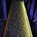
The goal of using the glass heart is to fully illuminate the entire heart when a TOY message comes in. This is done with an LED placed behind the heart. Because the LED will be placed directly behind the heart and the beam width of an LED even a diffused LED is pretty narrow something more is needed to diffuse its light. This is where transparent 3-D filament comes in.
- 3-D print a heart shaped cap that fits behind the heart
- Make the height of the tall enough to sit over the LED
- Attach the cap to the heart using any kind of transparent adhesive such as glue dots or hot glue
The LED that I used is a little 1W surface mount cool white dome LED. Any LED can be used as long as it fits underneath the cap. Because my LED is a surface mount LED, I soldered wires onto the leads, drilled two tiny holes in the false bottom in the center of where the heart will be mounted and fed the wires through to the back.
The Flower
Constructing
The flower shape was cut out of a piece of form board. Then it was decorated by my daughter. A stepper motor bracket and an axle-like rod with a flat end was 3-D printed.
The 4-wire bipolar stepper motor was pulled from some electronic device long ago, so I have no specs on it. Using some online help, I was able to discover the winding arrangement. The best part about the stepper is that it already had a pinion mounted on it.
Mounting
Pick a desired position on the false bottom panel. Drill a whole big enough for the axle-like rod to go through. 3-D print a stepper motor bracket. Attach the stepper to the backside of the false bottom panel.
3-D print an axel-like rod where one side it has a cavity to receive the pinion. Make the cavity width a tiny bit smaller than the width of the pinion. On the other side, make a wide flat disc shape where the flower will adhere to. Heat the pinion and push it into the axle-like rod cavity. This should create a nice snug fit. Drill a tiny hole to add a tiny set screw.
As for the flower, simply use glue dots or something to attach the flower to the flat disc.
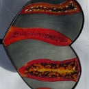
The Sculpey Flower
The 2nd flower in the 2nd TOY box is made from Sculpey clay. This definitely makes the flower much heavier. The stepper has to be strong enough to rotate this weight. Also, the fit between the pinion and the axle-like rod has to be extremely snug.
The LCD Display
Mounting
This is the simplest item to be mounted. Drill tiny holes for the screws and mount it down. Drill another hole to feed the 4-wire bundle through to the back.
The Picture Frame
Mounting
Depending on the picture frame and how it is to be mounted, it may need to be modified. I mounted mine to protrude outward to give it depth.
- Remove any hook or wire attachments and the free-stand leg in the back if they exists
- 3-D print 2 small standoffs where one end of the standoff is a thin flat disc. This will be placed directly behind the picture. Make the height of the standoff whatever height you desire. Make the standoff diameter large enough to create stability. The diameter of the flat disc at the end should probably be 2x that of the standoff.
- Drill two holes in the picture frame backing board large enough to fit the standoff through, one on each side of the picture.
- Fit the standoff through the backing board and reattach the backing board to the frame.
- Drill a tiny hole in the end of the standoff a bit smaller than the width of a tiny wood screw.
- Drill two tiny holes in the false bottom panel where the picture frame is to be mounted.
- Screw the wood screw through the false bottom panel into the standoffs.
The Illuminated Picture Frame
The 2nd picture frame in the 2nd box uses an EL panel behind the picture to illuminate it. Cut the panel to the size of the picture. Seal the cut edges of the El panel otherwise you may get shocked. Place the panel right behind the picture. Drill a hole in the false bottom to feed the EL panel power wires to back.
The Buttons
Constructing
The buttons are drawer pulls that sit atop the box. Their threaded rod reaches into the box where there's a Grove button mounted in a frame. Pushing the pull pushes the button.
- Find a place for 2 buttons.
- Drill holes in the box large enough for the pulls' threaded rod. It should be about 1.5x the diameter of the rod.
- Because the threads in the rod catch on the inside of the hole, carefully wind tape around the part of the rod that will be within the hole. Two or so windings should be OK.
- Optionally place a spring underneath the pull atop the box.
- On the inside of the box slide a washer and screw on a nut. The nut should be positioned so that ther is an amount of push available.
- 3-D print a bracket that holds the button right under the pull's threaded rod. Since the rod length is different from pull to pull, the brackets will be unique to each pull.
- It may be necessary to tweak the bracket position so that the rod makes perfect contact with the button. Washers between the bracket and box extend the length of the bracket if it's too short. A shim at the end of the threaded rod extends the length of the rod if the bracket is too large.
The Illuminated Button
The glass button on the 2nd box is a hollow glass drawer pull that is lit with an LED. A 10mm LED was cut in half and sanded to fit inside the opening of the glass drawer pull. Holes were drilled to feed the LED wires through and into the box.
Attachments

Step 4: The Hardware and Software


Hardware
I tired to keep with the standard set of Grove components. This reduced variability in the programming and reduced the level of effort of getting something connected fairly quickly. The electronic components consisted of:
- Intel Edison
- Arduino breakout board
- Grove base shield
- Grove buttons
- Grove LCD RGB backlight
- Grove I2C motor driver
- Stepper motor
- LED
- Grove EL Driver
The base shield made connecting everything trivial. There's very little work to do with the hardware. Most of the work was in the software trying to get things to talk to each other.
Software
I used Node.js and Javascript since both allow for very fast code iteration, which there was a lot of. Plus, I know Javascript and Node.js so when programming I could put most of my energy into the behavior. I also used Promises. This helped with the asynchronous nature of some of the components. Of course, I used MRAA and UPM. And although I really wanted to use Johnny-Five or Cylon.js, I stayed away from them because I didn't think I had enough time to learn them. Lastly, Pushbullet was used as the notification bus.
Latest changes here: GitHub: Thinking of You
Node.js
Node.js is very simple to use and understand. Start it, run some init code, and then create a long running loop, similar to the Windows message pump of old, and you're set. From here on out the system responds to events.
Promises
I used a fast and efficient implemenation of Promises called Bluebird. The code seemed a bit less cluttered than if I had used the standard callback idiom. Edison doesn't seem to have any issues with this library, though I didn't do anything really complicated or esoteric. I used just the basic stuff and it just worked. The primary reason why I used Promises is because I needed something like Arduino's delay() function. Delays particularly helped with LED fading where in order to see the change a delay has to occur between the brightness change.
Pushbullet
Pushbullet is a system where notifications to your device can be broadcasted to your other devices or computer. They provide an API which can, among other capabilities, allow one person's device to communicate to another person's device or computer just by referring to their email via a REST call. Using this system, each person will need their own API key to be able to send and receive notifications. Lastly, there's a Node.js package that provides an easy to use programming interface to Pushbullet.
Components
LCD Display
UPM I2C LCD provides a simple to use class to drive the LCD. By default, the display shows the date and time. It does this by displaying the date and time once every minute via an interval method. When a TOY message comes it, it is displayed on the LCD. To bring attention that a message has arrived, the background randomly changes color every few seconds.
Stepper Motor
The Grove I2C motor driver controls the stepper motor. UPM provides grovemd, an easy to use class to move the motor forward or background.
LED
The LED is nothing special. It connects directly to a PWM pin. Although a resistor should be used, I opted not to use one since it is rarely fully powered. When a message comes in, the LED will fade in and out. It gets near the high end only for a fraction of a second.
Buttons
I had varied success with the Grove Buttons. Out of five, two failed. It appears that they have a built-in pull down circuit. That was nice. I used standard MRAA GPIO instead of UPM Grove Button. The latter didn't have an ISR callback mechanism that worked in Javascript (at least it never worked for me). I had hoped they would have also dealt with the bouncing effect in the GPIO library. To compensate, I just used a delay which if there were click events with the delay period, they were ignored.
EL Panel
EL is quite easy to work with. With panels, they can be cut to shapes just so long as enough power is flowing to the panel. All that I needed just a simple rectangle.
Attachments
Step 5: Next Steps
There is a laundry list of things I want to add, change, and delete now that I built two boxes. Here's just a few ideas:
- Replace the store bought shadowboxes with hand-built, laser cut boxes. This would add to the personality of the TOY box as well as be able to come up with unique designs and shapes.
- Find a different way to mount the glass heart such that it is completely invisible. The hearts should appear as if they are floating.
- Get my kids to create the picture frames. More hand crafted items adds to the sentimentality of the message.
- Provide the ability for the sender to send a particular TOY message while still keeping it very simple.
- I'd rather not use my office's WI-FI. So, make one of the boxes use a cell phone to receive the message. A basic free cell service like FreedomPop might provide this ability.
- The first thing my daughter asked after pushing a button to send a message was "Now what?". The TOY box needs feedback that a message was sent.
- In addition, she wanted to animate the personal items in the box. So, allow the person to animate each of the items while maybe also sending a message at the same time.
- Create a way to replace the personal items. For example, since holidays are coming, make it possible to animate holiday items.
- Finally, I think that a kit or a Make-n-Take could be created so that others can send TOY messages to their loved ones.
Runner Up in the
Intel® IoT Invitational

Participated in the
Epilog Contest VII

Participated in the
Make It Glow! Contest


