

Introduction: Solar-Powered Robot


A while back I made dozens of robots which were in large part inspired by BEAM Robotics. For those unfamiliar, BEAM is basically a special method of robot building with an emphasis on biology, electronics, aesthetics, and mechanics (hence the acronym BEAM). One thing that sets BEAM apart from other approaches to robotics is its insistence on using radiant energy (predominantly solar power) and its tendency towards reuse and minimalism. While I heavily borrowed from the BEAM ethos and aesthetics, the robots that I built were not quite the same (they were all battery powered for starters).
Since BEAM robotics was such a large source of inspiration, I always wanted to try my hand at building a solar robot. However, rather than simply building another BEAM robot, I decided to incorporate solar into my own style of robot building. Instead of having it be powered entirely off the sun, I decided to incorporate rechargeable batteries. This means that at any given time the motors can be running off either the batteries or solar panel, depending on which can provide the most power. The solar panel is also recharging the batteries when the sun hits it. This allows the bot to run off of the sun, but not be entirely reliant upon it to move.
I think my approach merges the two styles nicely, and is a fun and simple experiment in robot building.
Check out my book Homemade Robots for more projects! |
Step 1: Materials

You will need:
(x1) Solar panel
(x2) Continuous servos
(x3) 1N5817 schottky diodes
(x1) 9V battery snap
(x8) AA rechargeable batteries
(x1) 8 x AA Battery holder
(x12) Zip-tie mounts
(x1) 2" wide aluminum ruler
(x2) Wall mount adhesive hooks
(x1) Misc. zip ties
(x1) Shrink tube
(Some of the links on this page contain affiliate links. This does not change the price of any of the items for sale, but I earn a small commission if you click on any of those links and buy anything. I reinvest this money into materials and tools for future projects.)
Step 2: Modify the Servo


Open up the servo case by removing the four screws from the bottom.
Desolder the circuit board inside and attach a red and black wire to each of the motor terminals.
Finally, crack open the gear box and find the gear with a little plastic tab on it that prevents continuous rotation. Simply cut the tab off the gear.
For a more in-depth guide to this, check out my other instructable on modifying a servo for continuous rotation.
Step 3: Drill


Drill a 1/4" hole in the center of the ruler, about 5/8" from one of the shorter edges.
Drill a second hole about 2-3/8" from the same edge.
Step 4: Bend


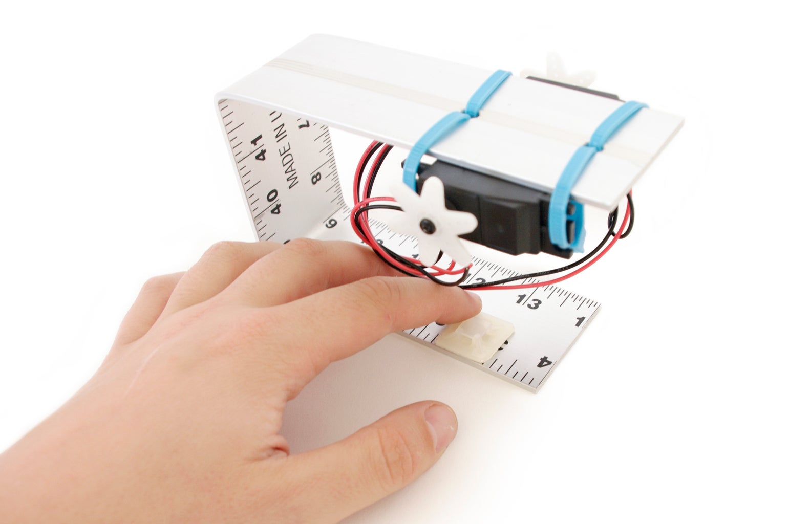
Using a table vise or two metal bars clamped to the edge of the table, make a 90 degree bend in the ruler at 6" from the edge that the holes were drilled.
Make a second 90 degree bend at 9" so that the ruler roughly forms a 'U'-shape.
Step 5: Attach


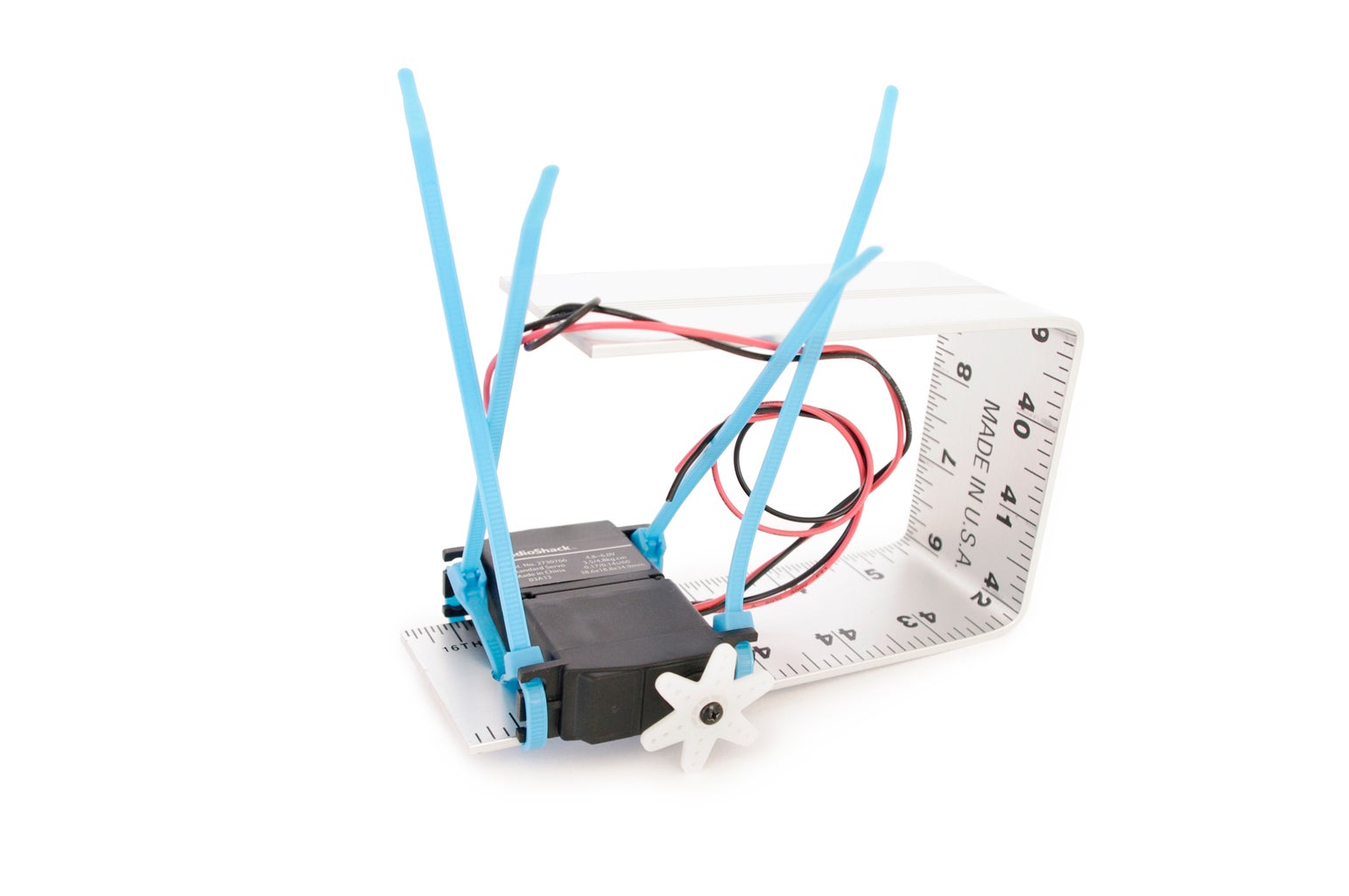

Zip tie the servos to the ruler using the two 1/4" holes such that the servos sit back-to-back.
Step 6: Zip Tie Mounts


Place two side-by-side pairs of zip tie mounts on the back of the solar panel. It is important that the channels of each pair are basically aligned.
Step 7: More Mounts


Attach two more pairs of zip tie mounts to the ruler on the inside of the 'U'-shape that is opposite the servos.
Step 8: Connect


Using the zip tie channel mounts, connect the solar panel to the ruler.
Step 9: Insert Batteries


Insert batteries into the battery holder.
Step 10: Diodes


Solder two diodes together such that the cathodes are connected (the side of the diode with the stripe).
Step 11: Build the Circuit
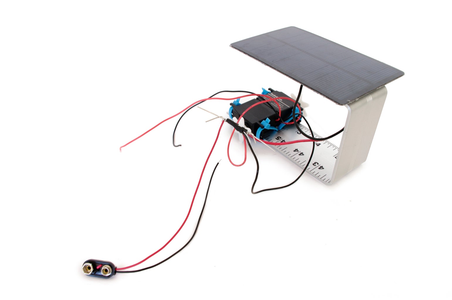


The circuit for this bot is based on a simple solar charging circuit by David Cook. The circuit has two schottky diodes connected cathode-to-cathode with one diode connected to the solar panel and one to the batteries. This setup allows either the batteries or the solar panel to be providing power to the motors, depending on which can provide the most current.
Since the batteries are also rechargeable, there is a third schottky diode connected from the solar panel directly to the battery back. This allows electricity to flow to the batteries and recharge.
To wire it up, first connect a red wire from one of the servos and a black wire from the opposite servo to the center point of the cathode connection.
Next connect the red wire from the battery snap to the anode of one of the schottky diodes. Connect the red wire from the solar panel to the anode of the other diode.
Once that is done with, solder the anode of a third diode to the red wire connected to the solar panel, and the cathode to the red wire from the battery snap.
Using shrink tube or electrical tape, insulate the wiring to prevent it from shorting.
Step 12: More Wiring


Solder together all of the black ground wires and the remaining free red wire from the servos.
This should leave you with two bundles of soldered connections; one for power and one for ground. Insulate both connections with shrink tube or electrical tape.
Step 13: Even More Zip Tie Mounts


Attach two pairs of zip tie mounts to what is essentially the underside of the 'U'-shape.
Step 14: Attach Batteries


Zip tie the batteries to the inside of the 'U'-shape such that they are held firmly in place.
Step 15: Trim


Trim the actual hook-part off of adhesive wall-mountable plastic hooks.
Step 16: Affix


Stick the modified wall mountable hooks to each of the respective servo horns (the thing that looks kind of like a gear).
Step 17: Plug In

Connect the battery snap to the battery pack and the robot is now fully operational.

Did you find this useful, fun, or entertaining?
Follow @madeineuphoria to see my latest projects.


