

Introduction: Speed and Cutting


Setting the Speed
USING THE CORRECT SPEED (RPM) IS ESSENTIAL FOR SAFETY AND TOOL LONGEVITY.
SPEEDS AND FEEDS CHART
Use the wall chart to determine the correct RPM, cutting speed and maximum depth of cut.
If desired, you can use the following information to determine a suggested RPM.
CALCULATING THE LATHE RPM
Setting the lathe to use the correct speed (spindle RPM) for the operation is important. Determining the correct RPM takes a combination of research, observation and common sense.
Common materials have a calculated value, called surface feet per minute or SFM, for the maximum speed that a tool can move through the material, without excessive wear or damage.
The SFM is used to calculate the RPM of the spindle and workpiece. RPM is based on the material being cut, the material of the cutting tool and the diameter of the material being cut.
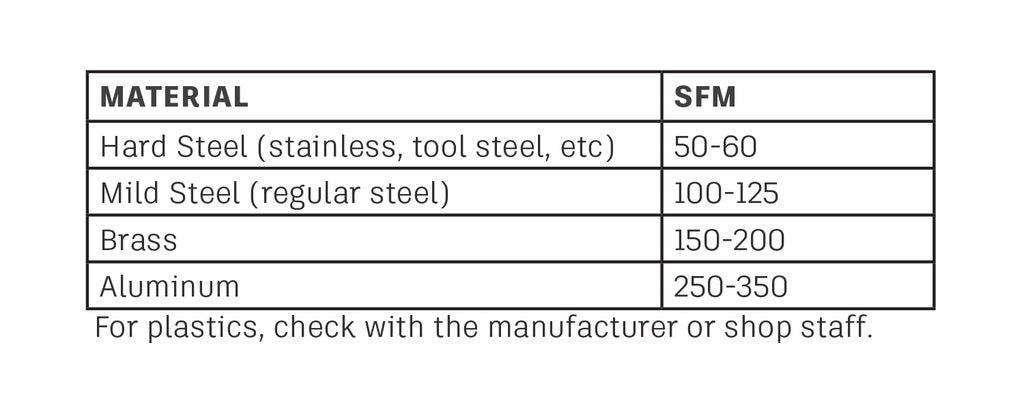
SFM of common materials cut in the Pier 9 workshop using the available cutting tools.
To convert the SFM to RPM, use the following formula:
RPM = 4 X SFM / MATERIAL DIAMETER
Example: 2" diameter stainless steel
4 x 50 / 2 = 200 / 2 = 100 RPM
Example: 1/2" diameter aluminum
4 x 300 / 0.5 = 1,200 / 0.5 = 2,400 RPM
Note: Observation and common sense will also help determine the correct speed. For example, if the tool is chattering and making lots of noise, something is wrong. Stop, look at the cutting tool, recalculate the speeds, and ask Shop Staff for help if needed. If the formula calculates an extremely high RPM, perhaps your math isn't correct. If you have questions about the RPM, see Shop Staff for help.
When it is time to start cutting, turn the spindle speed to a low number and start the spindle. Slowly turn up the speed until the readout is close to the calculated RPM.
PARTING AND DRILLING
When using the parting off tool, set the RPM to about 1/4 of the calculated value. When drilling, calculate the RPM based on the drill bit diameter, rather than the workpiece size.
- Using a small drill bit will calculate a high RPM. If the workpiece is large, you may need to reduce the RPM for safety. See Shop Staff if you have any questions about RPM.
Step 1: Cutting Operations
THE BASIC OPERATIONS WILL ALLOW YOU TO MAKE MANY DIFFERENT SHAPES.
There are 5 commonly used types of cutting operations.

- Facing
- Removing the end of the workpiece, to make it flat as well as perpendicular to the length.
- After facing, but before moving the carriage along the Z axis is a good time to set the Z axis to ABS 0.
- Turning
- Removing material along the Z axis of the workpiece.
- The remaining material can be cylindrical or tapered.
- Profiling
- Using a shaped cutting tool to create a feature, usually a radius or chamfer, on the part.
- Parting
- Cutting straight into the workpiece along the X axis, in order to cut it to length.
- Reduce the RPM to 25% and use lots of cutting fluid when parting.
- Drilling
- Using a drill bit to drill into the end of the workpiece.
Other lathe operations are possible, but not covered in this class.
+ Boring
- Using a cutter to create a hole in the end of the workpiece.
- Similar to drilling, but it's more accurate and the
hole can be made any diameter, or even conical.
- Threading
- Cutting threads on the inside of a hole, or the outside of a shaft.


