

Introduction: Split Flap Display
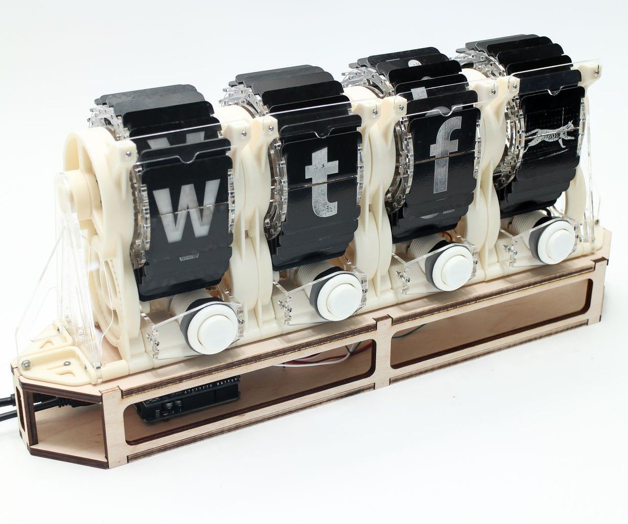


More and more, we're communicating with 3-letter abbreviations. BRB, LOL, WTF, etc. Smart phones, although convenient, are also adding to our disconnection from objects as things made by humans. This Split Flap Display brings text and animation back to its mechanical roots.
By pushing the buttons, you cycle through all the letters of the alphabet to spell out your thoughts in acronym form, and the last frame is an animation of the very first cat video (by Eadweard Muybridge). Why use high-resolution, multi-functional devices when you can get back to your industrial revolution roots?


Step 1: Tools + Materials
This project was designed (like pretty much all of my other projects) with Fusion 360. It's free, it's powerful, it's easy to learn, and the mechanical assembly tools make a project like this much easier than it would be otherwise.
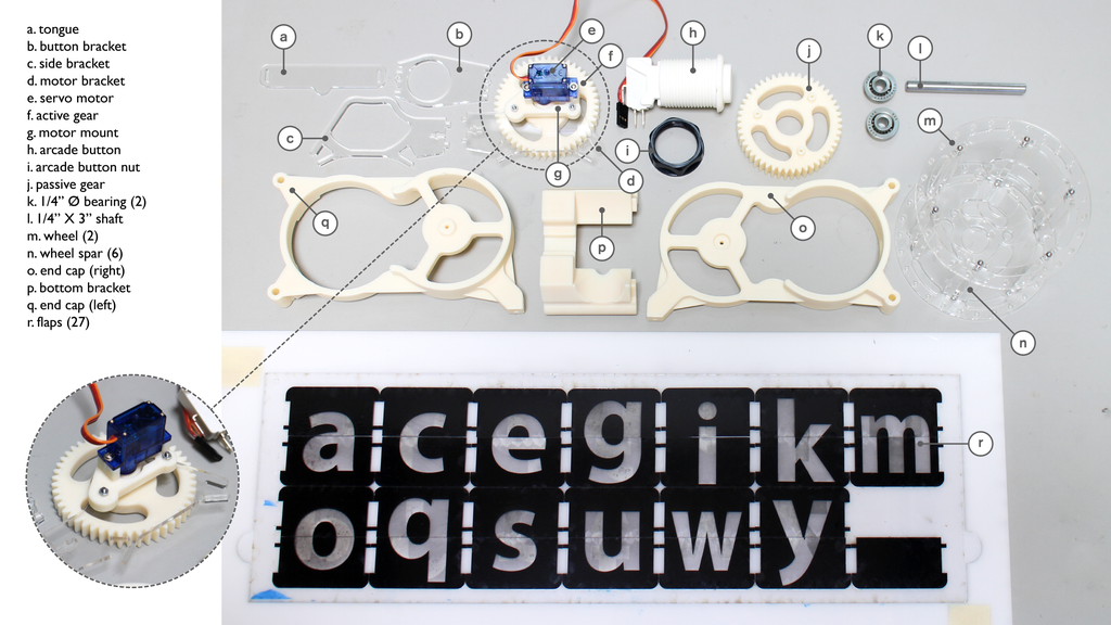
3D PRINTED PARTS
The white parts are 3D printed on the Fortus 450mc we have at Pier 9. This is a high-end production quality machine, but there's no reason you couldn't make this project with a consumer grade desktop 3D printer. This machine is awesome because the resolution is much higher than my desktop machine. The thinner layer thickness makes for smoother surfaces, and it prints in ABS, ASA, and a number of other super durable materials. It also has a separate material for support structures that's soluble in a lye bath we have in the lab, so it makes for excellent results with minimal effort. If you don't have access to a 3D printer, 3D Hubs or Shapeways can print the parts for you.
ACRYLIC PARTS
The acrylic parts are laser cut on the Epilog laser cutters we also have at the Pier. I used 1/8" (3mm) for the brackets, wheels and spars, and 1/16" (1.5mm) for the tongue and the flaps. I painted the flaps and etched them on the laser to get the letters and the cat animation- I'll get into that process later. If you don't have access to a laser cutter, Ponoko can do the cutting for you. The etching is another story...
ELECTRONICS
I used an Arduino Uno to control the servo motors by way of arcade buttons. Here's a full list of the electronic parts:
- Arduino Uno: $15.25
- Adafruit Motor Shield: $17.50
- Arcade Buttons (White), 28mm mount hole: $12.99 for 6-pack
- Continous Rotation Servo Motors: $15 for 2-pack
- 5V 10A Power Supply (for servo motor power): $25
- 5V 2A USB Power Supply (for Arduino): $6.95
HARDWARE
I used M2 machine screws and nuts for all the fastening. The quantities below are per display module. The configuration I built has 4 modules, but you could build as many as you want and connect them. The Arduino motor shield has 16 channels, so if you want more than than that you'll have to find another means of controlling the rotation.
- M2 X 6mm Button Head Socket Cap Machine Screw: 56 total per module: $8.04 for 25-pack
- M2 X 12mm Button Head Socket Cap Machine Screw: 8 total per module: $7.44 for 25-pack
- M2 Hex Nuts: 64 per module: $2.08 for 100-pack
- Ball Bearing: Open Flanged, 52100 Steel, for 1/4" Shaft Diameter, 11/16" OD: 2 total per module: $3.55 ea.
- Miniature 12L14 Drive Steel Shaft 1/4" OD, 3" Length: 1 total per module: $3.44 ea.
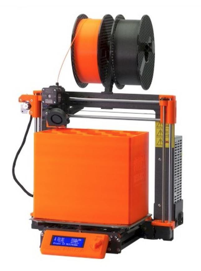
I use a Prusa I3Mk3S for just about everything. It's the best bang for your buck, in my opinion- very well made, 3D printable replacement parts, accurate and reliable.
PLYWOOD BASE
To keep the modules secure while pushing the buttons, I made a simple laser cut plywood base. This is just cheap 1/4" birch plywood.
Step 2: Design

I found this old patent drawing of a split flap display to get a sense of what the right way to build it might be. It's pretty simple. The characters are split between two flaps, the flaps are hinged on a rotating spool, and there's a catch / tongue at the top to keep the upper flap from falling down.
This drawing depicts a display (probably for a clock) that only has numbers, so only 10 flaps are needed (1-9 and 0). I wanted mine to use text, so I went with 27 flaps (a-z and a blank).
This was pretty much all the info I needed to get going. With hardware models downloaded from McMaster Carr, I was able to figure out the motion of the different parts, the placement of gears and servos, and plan everything out before I started fabricating.


The STEP file in this step is the full model of the module pictured here. The STL files are ready for 3D printing. UPDATE: The PDF and AI files in this step have the full laser cut layout. It's got multiple copies of the parts, so be sure to only cut the number of parts you need.
Here's a link to the Fusion 360 file: http://a360.co/29RAbPO
Fusion 360 is free for students and hobbyists, and there's a ton of educational support on it. If you want to learn to 3D model the kind of work I do, I think this is the best choice on the market. Click the links below to sign up:
Attachments


Step 3: Split Flap Layout

The split flap layout with text was a bit tricky, but once you understand the concept it's pretty simple. Basically the "front" of each flap pair is a whole letter, and the "back" of each flap pair has the bottom of the next letter and the top of the previous letter. So "a" has the bottom of "b" behind its top flap, and the top of "z" behind its bottom flap.
The laser layout for the text modules looks like this:

Front layout

Back layout
The laser layout for the animation module works the same way as the text- the "front" of each flap pair is a whole frame, and the "back" of each flap pair has the bottom of the next frame and the top of the previous frame. The animation layout looks like this:

Front layout

Back layout
Step 4: Fabrication
The laser cutting was by far the most time-consuming and difficult part of the process. To get the etched letters to show up clearly, I painted the 1.5mm acrylic with a layer of white acrylic paint, then once that was dry covered it with a layer of black acrylic paint. That way I was able to dial in my etch settings so that the laser just burned off the black paint layer, leaving white letters on a black background.

Etching on Front Side of Layout

Etching on Back Side of Layout (Flipped Along Vertical Axis)

Cutting Complete (Back Side of Layout)
With the laser cutting complete, I moved on to assembly...
Step 5: Module Assembly
The drawings below spell out the assembly process in detail. Nut pockets are built into the 3D printed parts, and the acrylic parts all have t-slots. No glue is used because you never know when you might need to take it apart and replace something.


The hardest part is inserting the flaps. The trick is to assemble the wheel so that the screws and nuts are very loose- just barely held together. That way you can click the flaps into place one-by-one, then tighten all the screws once the flaps are in.

Step 6: Base Assembly
The base is pretty simple- it's just a hollow platform for the the flip display modules to sit on with brackets at each end to keep them secure. I made some plugs (pictured below in the drawing) that keep the modules together and prevent them from moving around when you push the buttons.
The PDF in this step has the laser cut layout for the 3mm acrylic and the 1/4" plywood, the STL files are ready for 3D printing, and the STEP file is the full assembly of the base.


Step 7: Electronics + Code
CIRCUITRY
- Analog Inputs: Pins 2-5: Button inputs. The arcade buttons are momentary switches, so one switch lead goes to ground and the other goes to the corresponding analog input on the Arduino.
- Servo outputs: Terminals 0-3: Servo motors. These are built into the motor shield and the servos connect directly to them.
CODE
A lot of this code probably isn't necessary, but it ain't broke so why fix it? If you wanted to add more modules, you'd just add servo variables and button variables.
<p>/*************************************************** <br> This is an example for our Adafruit 16-channel PWM & Servo driver Servo test - this will drive 16 servos, one after the other</p><p> Pick one up today in the adafruit shop! ------> <a href="http://www.adafruit.com/products/815"> <a href="http://www.adafruit.com/products/815</a"> http://www.adafruit.com/products/815><p> ></p><p> These displays use I2C to communicate, 2 pins are required to interface. For Arduino UNOs, thats SCL -> Analog 5, SDA -> Analog 4</p><p> Adafruit invests time and resources providing this open source code, please support Adafruit and open-source hardware by purchasing products from Adafruit!</p><p> Written by Limor Fried/Ladyada for Adafruit Industries. BSD license, all text above must be included in any redistribution ****************************************************/</p><p>#include <wire.h> #include <adafruit_pwmservodriver.h></adafruit_pwmservodriver.h></wire.h></p><p>// called this way, it uses the default address 0x40 Adafruit_PWMServoDriver pwm = Adafruit_PWMServoDriver(); // you can also call it with a different address you want //Adafruit_PWMServoDriver pwm = Adafruit_PWMServoDriver(0x41);</p><p>// Depending on your servo make, the pulse width min and max may vary, you // want these to be as small/large as possible without hitting the hard stop // for max range. You'll have to tweak them as necessary to match the servos you // have! #define SERVOMIN 150 // this is the 'minimum' pulse length count (out of 4096) #define SERVOMAX 600 // this is the 'maximum' pulse length count (out of 4096)</p><p>// our servo # counter uint8_t servonum = 0; uint8_t servonum2 = 1; uint8_t servonum3 = 2; uint8_t servonum4 = 3;</p><p>void setup() { Serial.begin(9600); Serial.println("16 channel Servo test!"); //configure pin2 as an input and enable the internal pull-up resistor pinMode(2, INPUT_PULLUP); pinMode(3, INPUT_PULLUP); pinMode(4, INPUT_PULLUP); pinMode(5, INPUT_PULLUP);</p><p>#ifdef ESP8266 Wire.pins(2, 14); // ESP8266 can use any two pins, such as SDA to #2 and SCL to #14 #endif</p><p> pwm.begin(); pwm.setPWMFreq(60); // Analog servos run at ~60 Hz updates</p><p> yield(); }</p><p>// you can use this function if you'd like to set the pulse length in seconds // e.g. setServoPulse(0, 0.001) is a ~1 millisecond pulse width. its not precise.</p><p>void loop() { //read the pushbutton value into a variable int sensorVal = digitalRead(2); int sensorVal3 = digitalRead(3); int sensorVal4 = digitalRead(4); int sensorVal5 = digitalRead(5); //print out the value of the pushbutton Serial.println(sensorVal); Serial.println(sensorVal3); Serial.println(sensorVal4); Serial.println(sensorVal5); // Drive each servo one at a time Serial.println(servonum); Serial.println(servonum2); Serial.println(servonum3); Serial.println(servonum4); if (sensorVal == LOW) { pwm.setPWM(servonum, 0, 1200); } else { pwm.setPWM(servonum, 0, 0); } if (sensorVal3 == LOW) { pwm.setPWM(servonum2, 1, 1200); } else { pwm.setPWM(servonum2, 1, 0); } if (sensorVal4 == LOW) { pwm.setPWM(servonum3, 2, 1200); } else { pwm.setPWM(servonum3, 2, 0); } if (sensorVal5 == LOW) { pwm.setPWM(servonum4, 3, 1200); } else { pwm.setPWM(servonum4, 3, 0); }</p><p>}</p></p>
Step 8: Finished Product

Overall, I'm pretty happy with the finished piece. It works well when the cheap servos don't die out, and it makes a satisfying click-clack sound.
Since it's controlled by an Arduino, I was thinking about adding a black decal on the wheel part with a photo sensor lined up with it. That way, I could tell the Arduino what position the wheel is in. With that information, I could program the Arduino to spell out pre-programmed messages, or even make it controllable via Wifi.
Does some brave soul want to make 140 of these and make it write out a Twitter feed???


