

Introduction: Sponge Bot


This Sponge Bot demonstrates how through the addition of a simple mechanism, we can add a large amount of complexity to a robot. Using virtually the same electronics as my Single Motor Bot, we are able to make an entirely different and much more complex bot. This simple Sponge Bot uses a slider crank mechanism to translate rotational motion into a back and forth scissor-like motion.
In this way, even though the motor is rotating in a single direction, the legs seem to be moving back and forth in two directions. By using mechanical systems we are able to gain a wide range of motions from a single rotating motor.
For a crash course in robotics, check out my Robot Class.
Check out my book Homemade Robots for more projects! |
Step 1: Materials

In this lesson you will need:
(x1) Modified continuous rotation servo**
(x2) 2 x AA battery pack
(x4) AA battery
(x1) SPST toggle switch
(x2) 12" aluminum rulers
(x1) Swivel ball caster
(x1) Large jar lid
(x1) 2" plastic furniture slide
(x1) Permanent marker
(X1) 1" paintbrush
(x1) 5/16" x 1" bolt
(x1) 5/16" x 2" bolt
(x2) 5/16" nylon insert lock nut
(x6) 5/16" washers
(x1) 5/16" shaft collar
(x1) Sponge
(x1) Assorted zip ties
Step 2: Drill the Servo Horn


Once again, widen the outermost holes of the servo horn with a 1/8" drill bit so that they can accept zip ties.
Step 3: Mark and Drill


Center the servo horn on the plastic furniture slide and mark the mounting holes using a permanent marker.
While you can spend the time to calculate where center is, chances are you can probably eyeball it with enough accuracy for our purposes.
Once it is marked, drill four holes using a 1/8" drill bit.
This part will be used to space the mechanism's crank (i.e. rotating wheel) a slight distance above the motor and keep the fasteners from snagging while it rotates.
Step 4: Make More Holes


The lid is going to serve as the crank, and should be aligned on center with both the motor and the spacer.
Like we did with the furniture slider, we are going to center the servo horn, mark the mounting holes and drill with a 1/8" drill bit.
Note that the jar lid is placed upon a peice of scrap wood. I did this to avoid drilling into my benchtop when making the holes.
Step 5: Mark the Rulers


The nice thing about using rulers as building material is that they are easy to measure.
Mark the center of each ruler 5" inward from the end with the hole.
These will obviously serve as the robot's frame.
Step 6: Drill a Big Ol' Hole


We are going to want to drill a 1/2" hole through one of the rulers in order to pass through the servo motor's shaft.
Rather than start with a 1/2" drill bit, we are going to start with a 1/8" drill bit and gradually increase the size of the holes. This prevents potential disaster.
As the hole starts to increase in size beyond 1/4" you are going to want to clamp it down to prevent the part from kicking back.
To do this I used a bench vise, but you can also use some C clamps attached to the edge of your work bench.
Once I started to increase the size of the hole from 3/8" onward to 1/2" I also clamped the end of the ruler to the scrap wood with a C-clamp. This was to prevent the metal from bending upward as I drill and getting ruined.
In short, when drilling big holes start with small holes and increase the size gradually. Also, clamp things down well.
Step 7: Drill a Smaller Hole

In the other ruler, drill the marking with a 5/16" drill bit.
This will be used to attach the fixed end of the connecting rod (i.e. the paintbrush).
Step 8: Remove the Servo Horn


We will need to remove the servo horn so that we can pass the shaft up through the ruler.
Take a moment to loosen the screw holding the servo horn in place and remove it from the motor shaft.
Step 9: Mark and Drill the Ruler Again


Position the servo motor atop the ruler such that the shaft is centered inside of the 1/2" hole and the servo's longer end is pointing towards the pre-existing hole at the end of the ruler.
Mark the servo's mounting holes upon the surface of the ruler. It is easy to double check your measurements for this because a ruler practically measures itself.
Once all four holes are marked, drill them with a 1/8" drill bit.
Step 10: Make Another Hole


Measure approximately 2-3/4" from the ruler's edge and make a centered marking.
This is to indicate where to drill a hole for the toggle switch.
Since all switches are different sizes, you will want to make a hole appropriate to the size of the switch.
While measuring the diameter of the switch is a fairly safe bet, another thing you can do is insert the switch into the holes in your drill bit holder. The one it best fits into is the drill bit you should use.
In this case, we drilled the ruler with a 1/4" drill bit.
Step 11: Drill a Big Hole


To get the slider arm to move back and forth, we need to make a hole on the crank that is off-centered.
The distance between the offset hole to the center point of the motor will determine the amount the slider will ultimately move. In fact, it is easy to calculate. The final motion will be twice the distance between the offset and center. So, if it is an inch and a half off of center, the connecting rod will push the slider back and forth 3" total.
Drill a 5/16 hole approximately 1/2" in from the edge of the jar lid.
Even though I attempted to increase the size of the hole gradually, this is a fairly large hole to make in rather thin material.
Since my lid was not firmly clamped and I was using a hand drill, the hole did not come out pretty. In fact, it barely came out anything resembling circular - but it will do for our purposes (robotics is not exactly an exact science).
Step 12: Drill the Brush


The paintbrush will function as our connecting rod between the crank (i.e the jar lid) and the slider (i.e. the ruler opposite the one with the jar lid attached).
Drill a 5/16 hole through the center of the metal part of the paintbrush.
Step 13: Attach the Servo


Insert the servo's motor shaft through the 1/2" hole.
Zip tie it in place using the servo's mounting holes and the aligned holes on the ruler.
Trim away the excess zip tie tails.
Finally, firmly reattach the servo horn using its mounting screw.
Step 14: Attach the Crank Assembly


Pass four small zip ties through the four center holes in the jar lid, and then the four holes in the plastic slider.

Next, pass the same zip ties through the four holes on the servo horn.

Pull the zip ties tight, making sure their heads are positioned on the side of the lid facing the ruler.


Trim away the excess zip tie tails and make sure the wheel can spin freely without the zip ties colliding with the ruler. If any of them strike the ruler, cut away the offending zip tie and try again.
Step 15: Attach the Paintbrush


Take the paintbrush and insert a 1" bolt down through the hole in its handle. Then, slide three washers onto the bolt. These will be used to space the brush slightly above the wheel and keep it from snagging on the zip ties as it rotates.
Next, pass the end of the bolt down through the 5/16" hole in the jar lid.
Finally, lock it in place with a 5/16" lock nut. It should be tightened enough that everything is held firmly together, yet loose enough that the paintbrush can still spin around.
Thanks to the plastic furniture slider spacer, the lock but should rotate freely around without hitting the ruler. If it still collides with the ruler, you can either purchase low-profile lock nuts to replace it, or add an additional furniture slider as a spacer. Either should do the trick.
Step 16: Attach the Caster


Insert the caster's mounting shaft through the existing hole at the end of the ruler, and then slide on three 5/16" washers.


Next, slide on the other ruler onto the shaft of the caster such that the side with the paintbrush is facing up.


Finally, slide the shaft collar onto the caster's shaft. Press everything firmly together, and lock it in place by tightening the set screw using an appropriate hex wrench.
The two rulers should now pivot around the caster stem. When the connecting arm is attached to the ruler, this will cause the rulers to move in a scissor-like motion.

Step 17: Goodbye Marker


Pull the marker apart using a pair of pliers.
Take the body of the marker, and saw off the end to create a hollow tube.
Next, cut a section of tube that is approximately 1-1/4" long.
This will function as a spacer between the connecting arm and the far ruler.
Step 18: Attach the Brush


Insert a 2" bolt down through the brush, the plastic spacer made from the marker, and finally the corresponding 5/16" hole in the ruler.
Fasten the bolt firmly in place with a lock nut to keep it from unthreading.
The slider crank mechanism should now be complete. When you rotate the crank manually with your hands, the rulers should move back and forth.
Step 19: Insert Batteries


Insert batteries into each of the battery holders.
Be careful to keep any of the exposed wire leads from crossing and shorting the batteries.
Step 20: Attach the Batteries


Zip tie the battery holders centered upon the underside of each of the rulers.
Trim away the excess zip tie plastic as per usual.
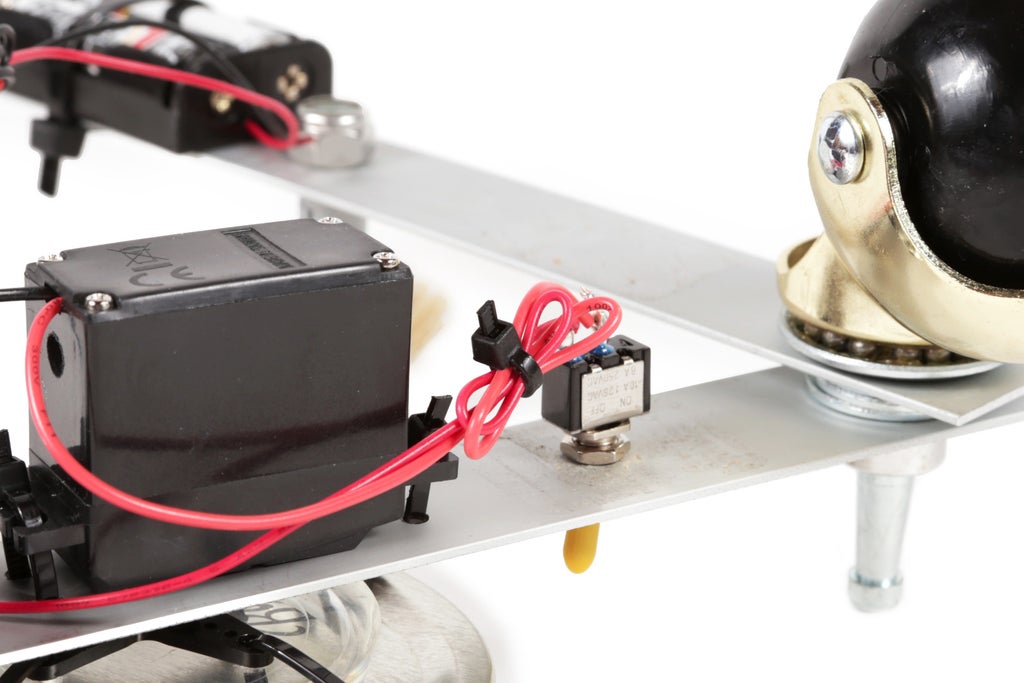
Step 21: Insert the Switch


Insert the switch into the 1/4" hole from below and fasten it firmly in place using its mounting nut.
Step 22: Wire the Switch


Solder the red wire from the motor to one of the metal terminals on the underside of the switch.
Solder the red wire from the battery pack next to the motor to other terminal on the switch.
Step 23: The Remaining Wiring


Solder together the black wire from the motor to the black wire on the unused battery pack on the opposite ruler.


Insulate this connection with heat shrink tube.

Twist the remaining red and black wires from the two battery packs together. If the motor starts to spin, flip the toggle switch. It should stop, and you should be free to resume soldering the connection between the two wires.


Again, insulate this connection with shrink tube.

Finally, clean up all of the wiring with zip ties.
Step 24: Part


Cut the sponge into two equal halves.
Step 25: Attach the Sponges


Pierce a zip tie through one of the sponges, loop it back and pierce it again.
Finally, zip tie the sponge to the end of one of the rulers.
Repeat the process for the second sponge.
Trim away the plastic zip tie tails and you should be good to go.
When you are ready, turn it on and observe how a single rotating motion can be harnessed to create a much more complex motion.


