

Introduction: Stargate Inspired Arduino NeoPixel 3D Printed Clock


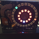
The Stargate DHD clock will display the time using NeoPixel LED’s oriented around a simulated clock face. The clock provides an hourly and half hour chime that can be turned on and off. The hours and minutes can be set via pushbuttons located on rear of the clock base. The center crystal on the DHD clock will illuminate on the hour and half hour for one minute. The illumination of the crystal is provided via a color changing RGB LED.
The hour is represented by a NeoPixel LED changing to red, the minute is represented by a NeoPixel LED changing to green and the seconds are represented by the NeoPixel LEDs changing to a blue color as the second’s increment. Using this method, reading the clock is very intuitive. As the seconds increase, each LED will change to a blue color. The Red (Hour) LED or Green (Minute) LED will not be overwritten by the Blue seconds LEDs.
The clock is 3D printed and utilizes one Arduino Uno, four NeoPixel rings and a real time clock. The Clock is controlled by an Arduino microcontroller. The Arduino handles the interface to the NeoPixels, chime speaker, LED center crystal and the four clock management pushbuttons.
The .stl files for printing the clock parts and the Arduino Uno code are located here and can also be found at http://www.guarnero.com. The included Arduino code also utilizes a pitches.h file that should be located in the same directory as the Arduino code.
The 3D clock dial and base are based upon the work of Techno35 at http://www.thingiverse.com/thing:49627
The dhd (dial home device) dial was resized so that it can print on a Lulzbot Mini printer and the dhd (dial home device) base was resized and heavily modified to provide a housing for the electronics.
The .stl files include the dial, base, ring sections for mounting the NeoPixels, crystal LED mount/cover, base cover and the crystal lens. The entire clock was printed with HIPS filament with the exception of the crystal lens which was printed with clear ABS. The clock is painted so any color filament will suffice.
A complete parts list is provided at the end of this instructable.

Step 1: Components - Arduino Uno R3 Controller

Step 2: Components - Arduino Proto Screwshield

Step 3: Components - NeoPixel 1/4 60 Ring


Purchased at:
Step 4: Components - DS1307 Real Time Clock

Purchased at:
Step 5: Components - Chime Speaker

Step 6: Components - Pushbuttons


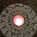
Step 7: Components - Cabochon

Step 8: Components - Cabochon LED
The cabochon is illuminated using a slow changing RGB LED. The LED will cycle between colors by just applying 5 VDC through a 200 ohm resistor on it.
The LED was purchased from Amazon.com
http://www.amazon.com/gp/product/B007RO9X82?psc=1&redirect=true&ref_=oh_aui_detailpage_o08_s00
The color changing LED that is illuminated for one minute when the clock is at the hour, 15 minute, half hour or 45 minute position.
Step 9: 3D Printing - Base

The entire clock was printed using a Lulzbot Mini 3D printer. The clock pieces were scaled and sized so they could be printed on the smaller print bed of the Lulzbot Mini. I used HIPS material for printing all parts.
Step 10: 3D Printing - Dial

Step 11: 3D Printing - Dial Ring

Step 12: 3D Printing - Cabochon/LED Holder

Step 13: 3D Printing - Cabochon Lens

Step 14: 3D Printing - Base COver

Step 15: Paint

Step 16: Construction - Glue the Four Dial Rings

Step 17: Construction - Glue the Dial to the Four Dial Rings

Step 18: Construction - Prepare the Parts for Painting

Step 19: Construction - Paint the DHD Base and Dial

Step 20: Construction - Mount the Cabochon and Diffuser to the Dial

Step 21: Construction - Glue LED Holder to the Dial Ring

Step 22: Construction - Wire the LED

Step 23: Construction - Paint the Dial Back

Step 24: Construction - Install the LED

Step 25: Construction - Install Pushbuttons

Step 26: Construction - Wire the Pushbuttons


Step 27: Construction - Wire the Chime

Step 28: Construction - Install the Chime

Step 29: Construction - Wire the NeoPixels


Step 30: Construction - Place Tape on NeoPixel Ring

Step 31: Construction - Run NeoPixel Wire Through Dial Ring

Step 32: Construction - Mount Dial Assembly to Base

Step 33: Construction - Wire Power Connection

Purchased at:
DC Power Jack Panel Connectors
http://www.amazon.com/gp/product/B00W8U70XU?psc=1&redirect=true&ref_=oh_aui_detailpage_o08_s00
DC Right Angle Extension
http://www.amazon.com/gp/product/B00QJCU580?psc=1&redirect=true&ref_=oh_aui_detailpage_o00_s00
Step 34: Construction - Wire Arduino to Components

Step 35: Construction - Program Arduino and Attach Mounting Base Plate / Bumpers

Step 36: Example Display

Step 37: Parts Listing


