

Introduction: Steampunked Solar Cell Uranium Light


I got steampunked in 2015 when my daughter asked me 'Dad, can we go to Elfia for my birthday?'. Elfia? What are you talking about? What on earth is Elfia? I replied. After a short explanation and a short discussion with my wife, the three of us went to Elfia in the Netherlands later that year: my daughter dressed up as an elf, including the pointy ears. My wife and I dressed as we normal do. BIG MISTAKE! My wife and I felt like strangers all day!
What a wonderful people are walking around in Elfia and by the end of the day, I was totally infected by the Steampunk Virus! No Antidote possible here! Since that moment, I have my own steampunk outfit (75% of this outfit is created by myself) and now I'm trying to create weird Steampunk devices.
Since I'm an absolute beginner on this subject, I have to start with small and simple projects and this is my first. My goal is to create good looking objects while keeping the project costs as low as possible, preferrably by reusing materials. I got inspired by the following project: Steampunked Magic Uranium Light by Junophor and decided to create my own version of a Steampunked Uranium Light.
In this instructable Í'm not going to describe everything in detail, because I assume you have some basic skills. If needed, I'll refer to other Instructables when I think more detailed information might be needed. One thing is certain, I really did enjoy making this lamp and I can't wait to start another Steampunk project.
Enjoy!
Step 1: Find and Buy Some Uranium Glass Beads

To create an 'uranium light' based on the one Junophor created, you first need to find a few affordable Uranium glass beads, so this became my first step: "Find and buy some Uranium Glass Beads".
To find some uranium Glass Beads, I searched the internet and found a Czech website where they sell this type of Uranium Glass beads. I bought a few 14mm Fire polished faceted round beads and some other uranium glass beads. The 14mm round Uranium Glass Beads are smaller than the 20mm beads used by Junophor, but perfect for the lamp I had in mind.
Step 2: Find and Buy Some UV-leds

When I go to an electronics shop in my country, I can get any led I want and also in various sizes, but...when I ask for an UV-led…I simply get 'No' for an answer and stay empty handed. I had to think creative. Once more, I searched the internet and found an UV-flashlight with 12 UV-leds on a Chinese website and I bought one because it was cheap and there were no shippings costs involved. When I received the flashlight, I took it apart, removed all UV-leds and stored them, with all other reusable parts, in a storage box for this project and future projects…
Step 3: Shortening a Test Tube

I already had two 30mm diameter, 200mm long test tubes. I shortened one of them to 90mm lenght using a dremel and a diamond cutting disc. During this process I worked in my garden, used eye protection, protective gloves and a dustmask because I definately didn't want to get glass in my eyes or glass dust in my lungs. For the same reason, I kept the rotation speed of the diamond cutting disc as low as possible when I started to cut the glass test tube.
What I did was: I used a waterproof marker to draw a cutting line all around the test tube at 110mm from the top.
After having done this, I went to my garden, put on the eye protection, the gloves and the dustmask, started the dremel at the lowest speed possible. with the dremel tool in my right hand, I touched the glass tube along the cutting line for short periods of time with the cutting disc, while rotating the test tube slowly with my left hand. As a result, the cut in the glass got deeper and deeper. At a certain moment I stopped using this method because I was afraid that the test tube would break.
For the next step, I removed the diamond cutting disc from the dremel tool and the spindle and continued the process manually by rubbing the diamond cuting disk over the cut while slowly turning the test tube. This took some time, but I managed to cut the test tube in half using this procedure.
Then I followed the steps as described in the following instructable : Polishing-Bottle-After-Cutting to polish the glass edge to make it smooth.
Step 4: Taking Apart a Solar Cell Garden Lamp

******************************************************************************************
Please note that you can use any (garden) solar light as long as you can disassemble it. This part of the instruction tells you only how I reused the electronics in my solar light. Also keep in mind that for this project the maximum solar cell size you can use is 60mm x 30mm
******************************************************************************************
The solar cell garden light I used for this project is a 2 Led, Solar Outdoor, Waterproof Ground Light with a 100mA Solar Panel, 2 Rechargeable 600mAh AAA 1,2 Vdc batteries and 2 super bright white/warm leds which I bought for a few euro's at a local shop. Taking apart the solar light and removing the electronics was quite easy, except for the solar cell which I totally wrecked. The solar cell was replaced with a rectangular solar cell I already had.
The battery holders used in the Garden light could be reused. When removing the Solar Light electronics, I also carefully removed the battery contacts from the battery holder, leaving only a plastic disc with an accidentally broken solar cell on top and on the other side two battery holders. The defective solar cell was removed by using a screwdriver, prying the screwdriver under the solar cell and then lifting the screwdriver up. Once the solar cell was removed, I turned the disc around. To cut out the two separate battery holders, I used a sharp hobby knife and cutted twice in a straight line alongside the battery holder, then bend the plastic to break the plastic along this cut. For each battery holder, I had to repeat this procedure four times.
Warning!
Be careful when cutting in hard plastic! It's easy to hurt yourself when using some pressure while cutting a straight line in hard plastic. Use some special 'knife proof' protective gloves when doing this. Your knife can easily slide away in the wrong direction...and it will definitely find your 'easy to cut' hand during this process. So be careful and be warned!
After having cut out the battery holders, I used the sharp knife again to clean them up a bit. Then I placed the battery contacts and the batteries back to these two battery holders.
Step 5: Modifying the Solar Cell Electronics


I already replaced the broken solar cell with a solar cell I already had. The next step to do was to remove both bright white leds on the circuit board and replace them with only one UV-led that I removed from the UV-Flashlight. I didn't solder this led directly to the circuit board, but used approximately 7cm electronics wires to create a little distance between the circuit board and the UV-led. The last step was replacing the push button switch with an industrial looking rocker switch.
Note:
A led is acting like a diode. When replacing a led, make sure that the + (Anode) and - (Cathode) are in exact the same position as the removed led. If you switch the leads, the Led will NOT light up.
If you need more information on 'how a led works', I advise you to take the 'Electronics-Class' and pay special attention to chapter nine: 'Diodes'. To help you for now, just take a look at the picture about the diode. If you take a closer look, you'll see which part is the positive and which part is the negative lead.
Step 6: Creating a Wooden Box.


The next step was creating a small wooden box. I had a left over piece of 4mm thick wood. From that piece I cut 4 smaller pieces for the side walls, size 60mm x 76mm, and 2 slightly larger pieces, one size 96mm x 96mm and another size 105mm x 105mm, for the top and bottom cover. I glued two side wall pieces perpendicular together at the long end of the wood pieces, making sure that the angle is exactly 90 degrees. I did the same with the other two sidewall pieces. When dry, I glued these two parts together, making sure that each side is exactly 80mm wide and that, seen from the top, the diagonals from the lower left corner to the upper right corner and from the lower right corner to the upper left corner have the same length. This way, you create a perfect square box when seen from above. During this process I used wood glue, sticky tape at the corners and a carpenter's square to keep the wood pieces in a perpendicular position. Now I had a perfect square box, all sides 80mm wide and from bottom to top 60mm high.
Now I had to draw four diagonal lines to determine two drill marks in the center of what would become the front and the back of the square box : two on the front (you choose which side becomes the front) and two on the of back the square box. The first two diagonal lines were drawn from the lower left corner to the upper right corner and from the lower right corner to the upper left corner, creating a drill mark in the center of the Front. The last diagonal two lines were drawn as described on the back of the box, creating a second center point on the back of the square box. The holes were drilled later. Then I cut another 8mm x 8mm square stick into 8 smaller, 88mm long pieces and glued these to the outer top and bottom edges of the box to create some sort of rim on the top and bottom. I also cut four 8mm x 8mm x 60mm long pieces and glued these to the inner corners of the box to make it stronger and also because I need this extra wood material at a later moment.
For the next step I had to draw a few lines on the piece of wood for the top cover. The first four lines were drawn over the full length, 14mm from each edge creating a drill mark at each corner, the point where two lines cross each other. The next two lines were diagonals drawn from the lower left corner to the upper right corner and from the lower right corner to the upper left corner also creating a drill mark in the center of the top cover. I used some small wood clamps to keep the top cover firmly attached to the top of the square box and drilled 4 vertical 5.5mm holes with a drill press, approximately 12mm deep using a wood drill and the four drill marks in each corner.
Before removing the wood clamps, I marked two sides on the top cover and the square box, making sure that, when removing the clamps and the top cover, I could place it all back in the exact same way after drilling the holes. Then I removed the wood clamps and the top cover and drilled a 12mm hole in the front of the box for the rocker switch and a 3,0 mm hole for the solar cell wiring. Finally I used a sanding block to remove all glue stains and to clean up the square box.
To finalize this step, I took a threaded metal rod, Size M5, and cut four 20mm pieces. I rounded al ends with a metal file to prevent issues when screwing a cap nut on these small threaded metal rods later on. After making sure that these rods fit in the four holes on top of the square box, the top cover can be place over them while leaving about 6mm of rod visible, and then I removed all and used a tiny amount of two component epoxy glue to fix these threaded rods in these holes. Make sure that no glue gets in the treads while glueing. I also glued the bottom of the square box to the bottom cover.
Have a look at the drawings.pdf and the pictures to see the result so far.
*) When drilling a hole in a piece of wood, use a leftover piece of wood at the back of the piece of wood to prevent the wood from damaging at the drill exit point
Attachments

Step 7: Time to Solve Some Issues


Now I had a few other issues to deal with...
- How do I attach the glass test tube on top of the top cover?
- How to place the led in such a way you hardly see the blue UV-light?
- How keep the bead above the led 'as if' it is floating?
To start with the first issue: "How do I attach the glass test tube on top of the top cover?". This kept me occupied for quite a while until I saw a rubber ring. At that moment the solution was clear: Create a wooden ring in which the test tube fits 'a little tight' to prevent it from coming apart from the top cover. So...I used a compass to draw two circles with the same center: 1 Circle with a 28mm diameter and another with a 33mm diameter. Then I cut out the inner circle and cut out the outer circle leaving a wooden ring. Then I started to sand it down to make a perfect, but a little tight fit for the glass test tube and I rounded the edges on the outside of the ring. This idea works like a charm.
The second issue was resolved in a short time. I took a telescopic antenna apart using a pipe cutter. Now having several metal tubes, I took the thickest tube and cut a 20mm part with the pipe cutter and glued this part carefully to the inside of a small led reflector with the two component glue which I used in an earlier step. This confined the light beam from the led quite reasonably. Knowing this, I drilled a 20mm hole in the center of the top cover, used some sandpaper to make the tube fit and glued the tube with led reflector to the top cover.
And the third issue was also solved in a short period of time thanks to a clever remark of my daughter: Why don't you glue the bead to the inside of the test tube? Simple but absolutely brilliant! With the bead very loose attached to a thin stick, I used a tiny drop of a very strong, but clear glue and attached it to the inner top of the test tube.
Then it was time to add the solar cell electronics. I took the solar cell apart from the circuit board, leaving the wires attached to the solar cell. The wires went through the hole in the back of the wooden box and I used some two component epoxy glue to glue the solar cell to the back of the square wooden box. While this epoxy was drying, I cut four sticks from a 30cm x 3mm x 3mm stick which was used for cotton candy. These sticks were then used to create a frame around the solar cell. This is a simple task and what size sticks to cut depends on the (replacement) solar cell you are using, so this is something you have to figure out yourself. When the glue was completely dry, I soldered the solar cell wires back to the circuit board to their right positions, placed the rocker switch and glued the two battery holders to the bottom cover.
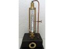
From this point on, the project is going to look like a weird machine.
Step 8: The Last Things to Do


Now it is time to finish the project. I decided not to paint the square wooden box but to use brown shoe polish. The reason for this is that the wood grain is still visible and it provides a worn, antique and weathered look. After a few hours, the shoe polish was dry and I glued four 4mm x 4mm L-shaped brass corner profiles to each outside corner. The length of each corner profile is 44mm. Four M5 brass cap nuts were screwed on the four threaded rod ends to keep the top cover in place. The only thing that bothered me was the silvery tube in the top cover center. I could have painted it in a brass paint color, but as if it was meant to be, I had a golden/brown plastic nose cap, as used in Chinese fireworks, lying around. This became the perfect solution to this problem. This plastic nose cap was a little too wide to fit to the inside of the glass tube. Rubbing the bottom over a piece of sandpaper until it fitted in the glass tube was the solution. Then I drilled a 3mm hole in the top, placed the tube back on the top cover and.....I finished this project!

Participated in the
Lights Contest 2017


