

Introduction: Student Proximity Sensor- Ultrasonic Sensor and Piezo Buzzer

Materials:
Arduino Uno
Breadboard
USB Cable (to connect the Arduino to the computer)
HC-SR04 Ultrasonic Sensor
Piezo Buzzer
10 jumper wires
Skill level: Beginner
As a teacher, there are many things related to student contact that can cause stress, but two things I can address with this project are both proximity-related. The first problem is that during my prep-time or after school students unintentionally sneak up on me. This causes me to be startled and have a nice adrenaline shot when I do figure out they are there (I have always been a person who startles easily). The second that sometimes occurs is that a student gets too close and invades my “space bubble.” By creating a proximity alarm I can address either of these issues.
The HC-SR04 Ultrasonic Sensor can be used to activate a piezo-buzzer to inform me when someone is coming near my desk, or to alert a student that he or she has come too close. The HC-SR04 Ultrasonic Sensor can be used to measure distances from a few millimeters up to four meters.
Aside from being an antidote for main-stream students who are close-talkers, it could also serve a useful purpose to help teach students with special needs about acceptable distance for communication. However, if I was going to use this with special needs students I would strive to create a more pleasant, friendly melody, rather than the single tone created by the model in this tutorial.
I had a great time designing my little model and I was pleasantly surprised at the ease with which I was able to learn the required elements. I am confident that anyone who has spent at least a couple weeks tinkering with DIY electronics could also conquer and improve this project.
Step 1: Get Ready!

Before beginning to build your “student proximity alarm,” be sure to collect all the necessary materials.
Step 2: Connect the Power and Ground Rails


In order to make it easier to space out the components, I connected both sides of the breadboard to power and ground. At the very top of the board I connected the power and ground of the left side and the right side together. Then, a few rows below that I connected the the red wire to the 5v pin on the arduino board and to one of the ground pins just below it.
Step 3: Setting Up the HC-SR04 Ultrasonic Sensor

In order to learn how to use the HC-SR04 Ultrasonic Sensor, I used this handy tutorial created by Dejan Nedelkovski at HowToMechatronics.com. It does a fabulous job of explaining the function, operation and coding of the sensor. So, instead of re-inventing the wheel, use this to set-up your HC-SR04 Ultrasonic Sensor. After you have completed the set-up of the sensor come back and we will add-on the fun features!
Step 4: Placing the Buzzer
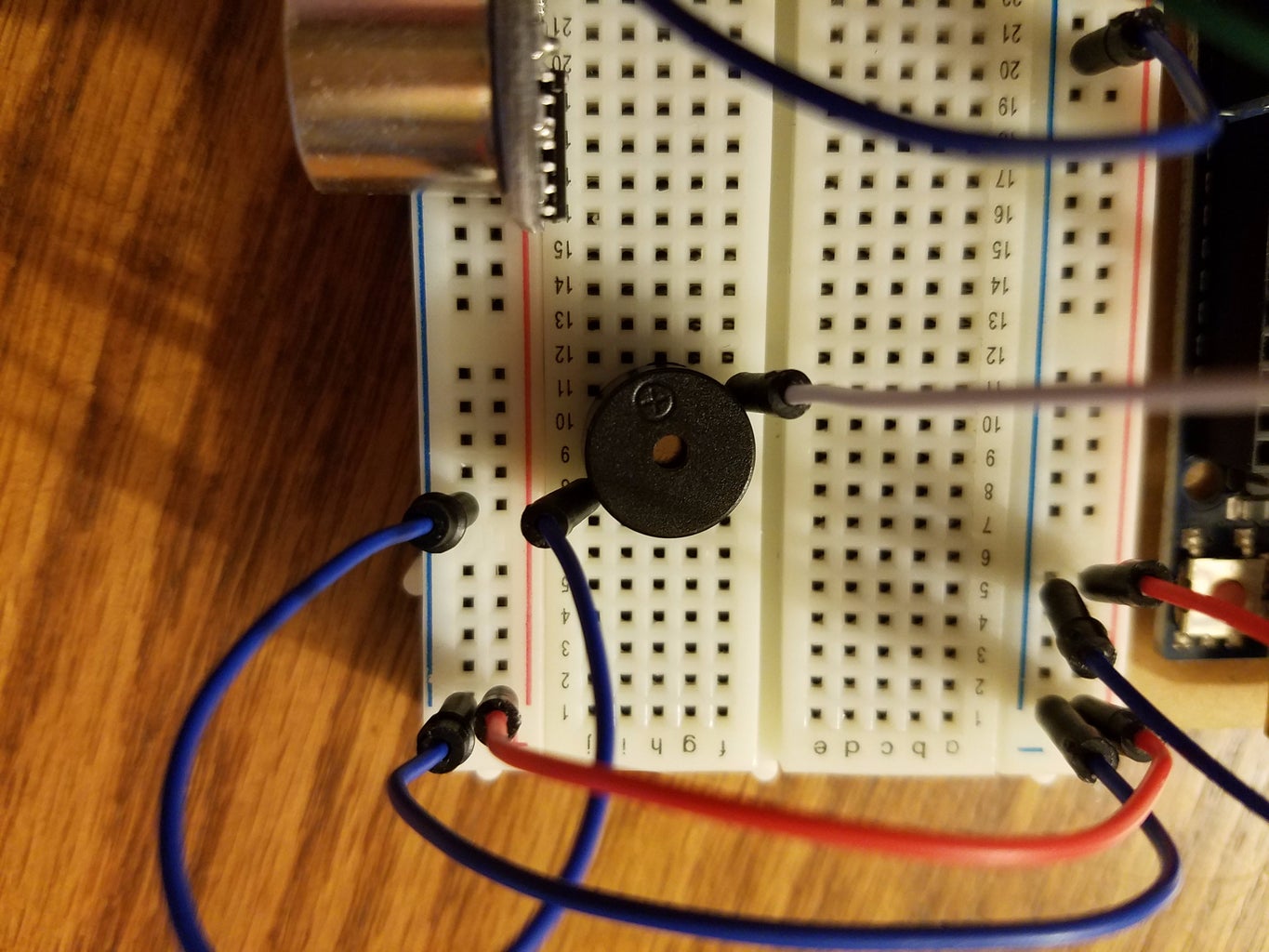
Now that you have set-up the ultrasonic sensor we can use it to activate other output devices like our piezo-buzzer. Start by inserting the buzzer into the breadboard with the two pins in the same vertical column and different horizontal rows. As you insert it, be sure to pay attention to what row numbers it is in to know where to attach the jumper wires. My buzzer is located in column H with the pins in rows 8 and 11. My 5-volt pin is in row 11 and the ground is in row 8.
Step 5: Wiring the Buzzer
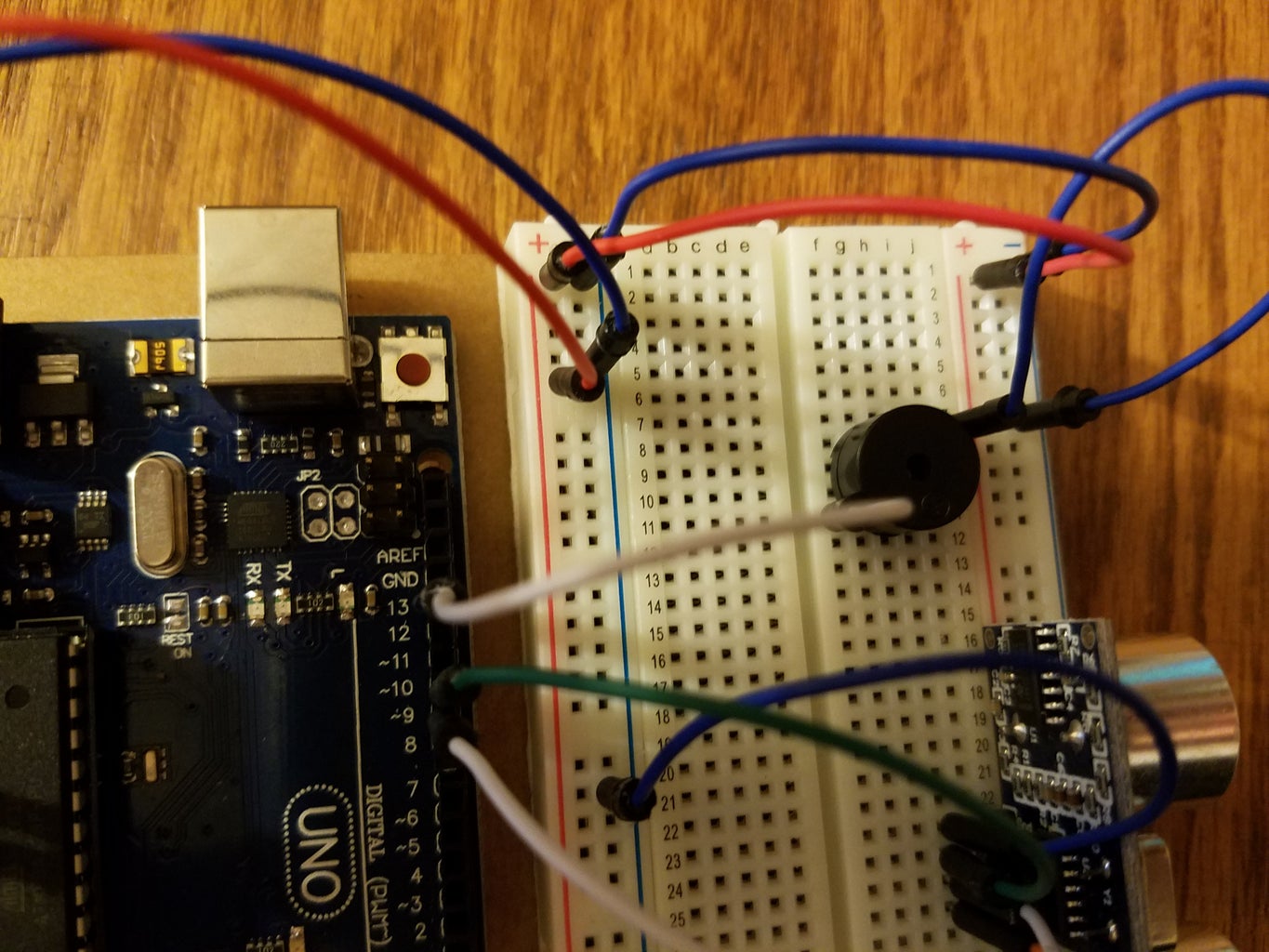

There may be a small plus sign on the buzzer element to tell you which pin is power. Connect the pin with the small plus sign (the 5-volt pin) to digital pin 13 on your Arduino board. (If you are comfortable manipulating code on your own you can choose any pin, I just chose one that would not cause visual confusion by crossing my wires.) Then connect the other pin to the ground rail on the breadboard.
I have all of my input and output devices on the far-side of the breadboard from the arduino board because I wanted more space, it doesn’t matter which side you use. If you put the input/output devices on the near side then you do not need the jumper wires that connect the power and ground rails on both sides of the breadboard.
(Due to the nature of how the fritzing diagram allows the pieces to be placed, the wiring of the ultrasonic sensor is opposite of what you see in the real images. The wires colors go to the same places, just in a different order.)
Step 6: Add a Few Lines of Code

In order to cause the buzzer to sound, we will use an “if statement” and the tone() function. To create the most basic version of the proximity sensor you only need a few more lines of code in addition to the code that is already operating the ultrasonic sensor. The code that will be added is:
if(distance <= 100)
{
tone(13, 440, 300);
}
The code for the ultrasonic sensor already established a variable of “distance,” so we can use this to variable again to tell our buzzer when to activate. Recall that the ultrasonic sensor was programed to output the distance of an object in centimeters. The code above tells the board "at a 'distance' of less than or equal to 100cm, execute the function tone()."
The tone() function has three parameters, the pin, the frequency and the duration. In the above example, it will activate pin 13, at a frequency of 440hz and maintain that for 300 milliseconds after the object has moved out of the specified range. Please note that with this code the buzzer will continue to sound until the object has moved out of the specified range. The number 300 milliseconds was just a random number I chose, you can choose whatever you want for how long you want the sound to stay on once the object has moved out of the path of the sensor.
Here is the full sketch:
Step 7: You're Done! Now, Make It Better!
Once you have inserted the above lines after the code for the ultrasonic sensor you have completed the most basic version of the student proximity sensor. Whoo-hoo!! There are many more opportunities for adding to this basic code. (The code for the following extensions is not included in this tutorial.)
One option would be to play a song instead of just a single tone. Sparkfun has a great tutorial explaining how to use arrays to play melodies instead of just individual tones.
Another fun project would be to change the tone as the distance measured by the ultrasonic sensor changes.
If using the project with special needs students, an RGB LED could be wired in to provide a visual cue in addition to an auditory cue. Green could show an acceptable distance, yellow is questionable and red is too close!
Share your success with these extensions in the comments below or in your own Instructable!!


