

Introduction: TABLE SAW SLED AND ADJUSTABLE ARMS


This instructable will show you how to make a super sled.
A super sled is designed as an all in one cutting table for your table saw, replacing the original mitre and fence.
the adjustable arms can be adjusted to any angle for any job type
I made this because my miter was insufficient and was having trouble cutting correct angles.
i have adjusted the text it should all be Arial 9 and all black text
thank you for your feed back
Please enjoy the instructable .
All feedback is welcome including
Constructive criticism..
..
Step 1: Tools Needed

Wood glue
Several G clamps
Long straight edge ruler
Router
Drill with ¾ and 3/8 bits
Heaps of sand paper
60 12mm screws
26 25mm screws
6 40mm screws
2 65mm batten screws
Pencil
Square with 45 degree pre set
Saw rip or tennon
Philips head screwdriver or bit for drill
Dowel x 2 and matching drill bit
Two steel rulers
2 triangular drafting square.
Chisel 5mm
Tape measure
Countersunk piece or 9mm drill bit
Step 2: Timber Needed
1 2x4 ft board >cut down to size
1 48 inch x 1 ¾ x 3 inch hard wood
1 8 ½ x 6 ½ hard wood
1 90 x 45 mm x 300mm (12 inches)
2 2 ½ ft thin plastic or runners timber
Step 3: Base


Draw a line from each corner to the diagonal opposite making a really large X on your board. They should intersect where your centre line is. Hopefully
You can do this in any order. Draw your x first then measure your centre line or mark the centre line first
Note:
I have called a hole where the router goes all the way through the timber a
Having a long writers block. lol sory
Step 4: Board Marking


Measure the distance from the side to the centre line. (18) inches
Mark your board on the long edge TOP and of course Bottom on opposite edge
find the ½ way measurement 9 inches and draw a line from top to bottom on either 3 ft edge
check your measurements with a diagonal X by drawing a new diagonals in each 1/4. Repeat on the opposite half.
You now have an X for the full board along with the centre line, an X on each half of the dividing centre line along with the X of those two sections.
If you look carefully you have 3 vertical lines dividing the board into 4, you also have 3 X’s. The first large one and two smaller ones, (one for each side.)
If this sounds confusing a quick glance at the picture will put your mind to rest.
if you have not,Now is the time to physically mark your board: top and bottom and front and back.
With each ¼, divide them again in half, checking them with the drawn X as above
Measure up 71 mm on the 3 ft line and drop a line across the width of your board.
Measure down from the 3 ft line149 mm from the top and drop a line across the width of your board.
Step 5: Drilling Set Up


Here, we are setting up the drilling points.
Your drilling points become the starting points for your router.
set up your press to have a backboard 71mm from the drilling point. or 149mm if your are drilling your 3/4 first
The lines marked at 71mm are drilled 3/8 or 10 mm
The lines marked at 149 mm are drilled ¾ or 19.5mm I only had a 19mm spade bit so 19 mm it was.
Step 6: Routing Between Drilling Holes


If you don’t have a 10mm or 3/8 bit you can make two passes set at different widths with your router
If you don’t have a straight edge you can always use the edge of your level.
start on the hole that is 10mm or 3/8. This is the smaller of the two holes you have drilled. Make your cut with the router bit all the way to the larger hole. stop without going past the larger end of the hole. making a slot from drill hole to drill hole.
This router cut makes a through and through slot which will be used to secure the sled to table saw at a later date.
Now set your router to remove a 6mm deep channel 19mm ,3/4 wide over the slot you just routered.
User a 19m diameter router bit or:
Draw a parallel line from the outer edges of the ¾ hole along the 6mm slot
if your are at all unsure see the picture below.
THIS SIDE IS NOW THE UNDERNNEATH. MARK IT "bottom" AND THE OTHER SIDE "TOP"
remember the edges besides the through slot are 6 mm deep.
Step 7: Routering


On the same side as your 6mm grooves we are going to make one long rebate set for a guide that will run in the miter slot of your table saw.
You will also need to make two (2) runners that fit snugly into the mitre channels of your table saw. I’ve used pine, but if you have any polyester strip or similar use that.
Once you have measured the width and length add two (2) inches to both ends before you cut them.
insert both runners in the miter slots on your table saw, and place the sled on top of your runners.
Looking at the centre line of the board, that is where the saw blade will eventually be and must be lined up accordingly before we continue.
Line up the bottom of your board with the bottom edge of the table saw keeping the centre line above the saw blade. I found using a straight edge sitting on the edge of the table saw helped.
When you have the board in the correct position mark accurately the position Of the left hand runner up on the edge of the sled, ensure you mark both ends of your board.
Take your time it will make all the difference.
NOTE :
Only mark the left hand side runner at the front and back. the other runner at this stage is just there to keep the sled level on the table saw. The right hand side is done a little different.
Now you have the width sorted out draw lines from front to back on the bottom of your sled. you will need to make a rebate into the base of your board.
I cheated here. I dropped several short nails from the top down to the runner on the left. Ignore the one on the right at the moment.
Flip the job over and run your pencil along the sides of the guide you nailed on.
Drill your counter-sinks, one in the centre and two one inch from each end. Insert a clearance hole in your runner and screw three screws into your sled.
Do not glue at this stage.
Keep in mind the screws length, we don’t want them coming through to top.
Place a arrow on the runner facing you.
undo them and place the runner aside keeping the direction of the front and back clearly marked to help attachment later.
Step 8: Runners


Once you have routed your correct width for our miter runner go ahead and glue it in.
Tap the runner evenly into the slot ensuring you have it sitting flat.
To test the accuracy of you’re marking and routing align the three holes you screwed in and secure them before going any further. Play around with the runner position until the screw holes line up perfectly.
If they don’t check your markings and play with the router until the runner fits correctly.
When your ready to proceed, Carefully place screws every 2 inches along the runner.
Remembering to check the length of your screws against the depth of your job, we don’t want any screws protruding on the working side of your job. Like I did by over countersinking 3 screws. Oops. lol
With such a thin runner I drilled clearance holes first.
Now we are going to attach the second runner to the board.
The process is similar to the left with a slightly different process, this is to make sure we keep it tight. no slop in our SLED, we all hate slop.
Tap the second runner into the right hand side track of your table saw.
There are several ways to do proceed from here. You may choose to do it differently but this is how I did mine.
With the right hand side runner sitting flat and snug into the right hand side track, I place the board on the table saw with the left hand runner in its grove. Align the front of the board with the edge of the table saw
With the board square to the table saw and having one runner glued screwed and the second runner in place I drove several long thin nails through the board into the runner but not before doing the following.
Here is the small variation that will make all the difference.
Before nailing, I pushed the sled board to the right ensuring there was no slop in the left hand side runner.
I also used two steel rulers and pushed the right hand side runner towards the centre of the table saw, again reducing any slop in the runners. Once you are happy you have removed all chances of slop, I dropped several nail into the rail via the top of the board.
With the nails firmly in place turn the project carefully over. I used several blocks to support the board base above the nail heads.
I once again drilled clearance holes into the runners so not to split my runners as they are very thin. I dropped three screws into the job and marked the runner in place with a sharp pencil.
With everything in position I remove the three screws flip the job over and remove the nails holding it in place. Flip it back again and you should see the runner has fallen away.
Ensure you mark the track showing which direction the runner was facing to make the aligning of the screw holes easier.
All I did here was run glue inside the pencil marks. I dropped the runner back in place securing the three screws back in place. Divide the runner into even spacing’s and add more screws to the job every 2 inches
See you all later while the glue dries.
When your job is dry, cut the entire overhang off with your hand saw, I use a block of timber to keep the saw blade vertical, love a neat cut.
Step 9: Rear Fence


Make the back board, this is the long board your future jobs will rest against when cutting. ( back board / rear fence )
MAKE SURE IT HAS A FLAT SURFACE AND THE BASE IS 90 DEGREES TO THE FACE. this will ensure all cutting in the future .
A joiner and plainer is normally used, I have neither so mine is like a dogs leg. I will fix it later.
I have a nice piece of red gum 88mm x 88mm by 1300 long, I’m dying to true it up and square it. it will look beautiful when sanded.
The rear fence board / fence guard measurements :
48 inches long
3 inches high
1 ¾ wide.
The next step is to bring your table saw blade up through the base of the sled board.
Align your sled board so the blade sits under the middle of your board and the edge of the sled closest to you is level with the edge of the table saw.
Turn your baby on and slowly wind away.
No need to move it yet just wind it all the way up then down.
To attach your back board to your sled, ensure the front edge is 90 degrees to the saw blade and you have trued your board up correctly. If you don’t you will never ever have a true square cut again, like me.
Place two steel rulers into the slot left by the saw blade in your sled. Clearly, After winding the saw blade all the way down . They should fit snugly.
Find or buy two triangle drafting squares. Place one each side of the ruler to set true 90 degrees on each side of the blade.
Keep one edge on the square on the ruler and the bottom edge against the rear fence you’re trying to square up. if your drafting square keeps moving use some double sided tape to hold the square in place.
Make sure the back of the back board / fence guard is as close a possible to level with the edge of your base. When the front is square look at the edge and if it back is over hanging plane or sand it down. No real reason except to make it look nice.
Once you’re happy with the accuracy, and trust me when I say make it dam accurate,
Slide the sled forward until you can get a clamp over the sled and the rear fence. Mine moved like too freely, perhaps I should not have sanded both surfaces so well knowing they were going to be screwed together.
Once you have several clamps holding it in place, check the back board did not move away from your drafting triangular squares.
Once you entirely happy, flip your job over and place screws every two inches.
I drilled clearance holes and countersink them, I did not glue it because I know I will have to take mine off to either replace the back board or at the very best have it straightened.
When the back board is glued, screwed and dry, place the runners in the appropriate slots on the saw table.
Turn on the power and run the blade through the back board / rear fence, at this stage cut no more than an inch from the top of your rear fence, you can do more later, once the handle is in place.
.
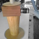
Step 10: Sled Handle Part 1


To make part 1 of the handle that will be fixed above the back board I used 2, 45x90’s glued, doweled and
Join them, you can join them any way you like.
The size I’m trying to get is 8 1/2 x 6 ½.
This block will give extra support to the rear fence now it is cut
I added some dowels to the job but it’s an optional extra. I’m prone to dropping things, the added support will help.
Mark your centre of your board width wise, this will align up with the centre line on your sled and also the centre line on your rear fence where the blade cut. While it is not essential to do, it will look more esthetic.
Give your job a serious sand, if you like that type of finish or leave it rough it’s all your choice.
I started with 60 grit then -80 – 120 -180 – 240 then a piece of very old 240 with a buildup of stuck wood to its surface, this give a nice polish to the finish.
As you can see I’ve gone overboard with screw holes but that’s just me.
Four would be fine.
The two single holes are to join an additional piece with dowel, making the top of the handle
I need short screws, but long enough to do the job, which I did not have, so I gave each a fairly deep countersink hole for the head of the screw. The four main screws, I used roof batten screws.
Step 11: Sled Handle Part 2


Next is the handle at the top of the two joined 45x90’s,
I feel quite uncomfortable at times with my hands flaying around over the blade. This will keep my hands well secured to the hand rail.
This is the top of the handle, where your hands will push and pull the sled across your table.
Made from one 90 x 45 X 8 ½ inches long. Sliced down the centre after shaping the edges were complete.
To make the groves I used my belt sander to round over the edges, you could use a router bit before cutting it down the center but I don’t have a piece that large.
I drop my little fingers into the side groves keeping my hands from moving while cutting.
Align the top edge of the detailed hand piece with the top of the two 90x45’s boards we joined earlier.
Place 2 dowels pieces in the 90x45 two solo holes mentioned earlier, drill and match the holes for Dowling in the detailed handle
Repeat this on the opposite side for the remaining back curved hand rail.
After gluing and the hand rail is dry sand the tops flat.
Step 12: Handle Comfort


Here I got a bit carried away with my handle. I shaped groves where my thumb knuckles sit, making it just a little more comfortable.
after 10 minutes of playing with the sled i worked out the sled will move more freely if i push and pull from above the runner position.
As i do, i placed groves and rolled the edge for comfort.
Step 13: ADJUSTABLE GUIDES and Stops.


Now I’m going to make 2 adjustable guides, call them anything you want.
Start with a scrap piece of ply 10mm thick 26 inches long. if you don’t have this size material use anything you have and adjust your measurements later.
Cut 4 strips 3 ¼ inches wide x 26 inches long. We shall trim it down as we go. You can make any length you like this is simply the length I wish to make it. i have also made one 6 inches shorter and one that is 6 inches in lenght.
DON’T FORGET TO TRIM THE LENGTHS DONW BEFORE MARKING YOUR ROUTER START POSITIONS, LIKE I DID.
Find the centre of the board width wise and mark it on both ends.
Mark out 45 degrees from the end, making an arrow shape, pointer shape or a triangle, just depends on how you look at it.
Once you have cut both ends on all 4 pieces stack them on top of each other and compare their lengths.
This will tell you nothing except how accurately you are marking and cutting.
If you lengths are not all even feel free to secure them together and cut them as one piece. You will only have to make 4 cuts. The down side is you will not learn to cut accurately.
DON’T FORGET TO TRIM THEM DOWN BEFORE MARKING YOUR ROUTER START POSITIONS, LIKE I DID. This is your last chance.
Number the 4 boards 1 2 3 4,.
Cover one side of board 1 and 2 with glue.
place number 3 on number 1 and number 4 on number 2.
Giving you 2 pieces to clamp up and wait for them to dry.
.
Step 14: Adjustable Slide - Markling Lines


We are going to measure the centre of the board, width wise, draw a line down its length, same as we did back at the start of this project.
Once you have found half way, divide each half in half again. This will give you 4 quarters.
Number your lines dividing your quarters, giving you numbers 1 2 3.
We will only be using line 1 and 3. the number 2 line being the centre is not used.
On the number 1 line anywhere within 1 inch from the end, draw a line across the board and where it intersects with the number 1 line, drill a 10mm hole, this will be the starting point for a through and through slot with your router. If you have a router table then this is going to be easy.
we are making a 10 mm slot just like in the bottom of our main board accept we are not having 2 size drill bits nore a 6mm grove over it.
Do the same to the opposite end. Keeping the distantness at the end the same on both drill points. Drop a 10mm hole, this is the ending point for your router bit.
Step 15: Routering the Adjustable Guide


starting at the drilled point.
finishing at the other drilled point
.
OK, WE HAVE A STARTING POINT AND A FINISHING POINT TO ROUTER, GO AHEAD AND ROUTER IT.
COPY THE PROCESS ON THE SECOND THE SECOND ADJUSTABLE GUIDE WE CUT.
This slot will be where the board is attached to your sled via the slots in the sled base.
note.
the side you router your 19 mm channel in is the top.
On line 3 we are going to drill a shallow hole parallel to the first hole you drilled. With one difference.
We are only drilling 6mm into the thickness of the timber. You can drill this hole to ½ the thickness of the timber if you wish. 6mm is all i needed.
The width of this groove is the same width as the shallow groove we made back at the beginning of the project in the flat board (19mm) wide.
DO NOT DRILL ALL THE WAY THROUGH.
Do not router all the way through
Go ahead and router your channel.
Word of warning, if you do not have a router table and are routing by hand and rail. If you put the rail of the router on the side of the timber with the through and through, it can flex and give you a bent channel. Lol again I learnt the hard way so you don’t have to.
next:
We are going to place a cover over the 6mm channel we just cut.
Measure the width from the edge of your board to the center of your adjustable guide. line 2
This is the width of your cover.
I used scrap lying around the room, masonite
Anything thin would be ok.
Align the outer edges together and mark out the center of the channel.
If you are unsure in any way please have a look at the attached pictures.
Glue and screw it to the adjustable guide, keeping in mind the positions of your screw lengths. We don’t want to blow the sides with screws aligned incorrectly.
I countersunk the heads to ensure a clean and smooth finish.
Find the center of your channel you just routed and mark it on the board you just screwed down.
Follow that line with your router using a 10mm bit (10mm = 3/8)
If you don’t have a 10 mm bit keep making passes until it is 10 mm wide.
Ensure the 10 mm Is in the center of the 19mm channel.
..
Step 16: Final Steps Supporting Board


We are now making the Supporting board at the front edge of the sled.
1, 45 x 90 x 30 (12 inches)long
cut two 45 degree angles, see pictures for clarity if unsure.
Find the center. (6) inches. Place a line down the face of your board.
The fence is glue and screws from underneath. (The longest edge of this board is lined up with the edge of the panel sheeting. Watch the placement of your screws as the blade will cut through this board like the mitering fence did.
There is no minimum length
of this front board so make it whatever length you feel will suite your job.
Stops for the adjustable miters.
I’ve not shown any details here because there are much better ones I have seen on instructables. I’m just am having problems finding them to add them here. Sorry
If you are having any problems with these instructions there are extra plans at the very bottom of this instructalbe.
I’ll add pictures of the stops but I won't add detail in the instructable.
Why? because I’ve seen much better ones on instructables that i intend to make for this sled.....
well done you’re done.
Hopefully, job well done
At the end of this instructable there are some details of the origin of the super sled and a web site to watch the original video I saw, each video goes for 10 minutes and there are 5, all in HD
Gee I wish I had his work shop.....
..
Step 17: Redgum Post Change Over


This is going to be my rear fence when its trued up. Old fence post ( red gum)
i will also make the opposite fence at the front of the sled out of this too.
Step 18: Eaglelake Woodworking Diagrams.


The plan came from eagle lake woodworking and was origanally constructed by John W Nixon in 2009
I played the video and took a tonne of notes while on pause.
http://www.eaglelakewoodworking.com/post/Super-Sled-Crosscut-and-Miter-Sled.aspx.


