

Introduction: Tempduino - Arduino Based Temp and Humidity Display


The temperature in my office at work varies quite a bit depending on the time of day, season, and the whims of the other people I share the floor with. When I’m sitting at my desk shaking uncontrollably or sweating profusely it would be nice to know if it’s due to the temperature or just work related stress. A simple $5.00 thermometer would suffice, but where’s the fun in that? Making my own thermometer might cost ten times as much, but I might learn something in the process and it would be way cooler than any cheap store bought thing? I’d rather make something myself even if I have to pay a “maker’s premium.”
Step 1: BOM
Bill of Materials:
DHT22 Temperature-Humidity Sensor + Extras (Aosong AM2302 + 10k 5% resister)
Adafruit Perma-Proto Half-Sized
Adafruit 0.56” 4-Digit 7-Segement Display w/I2C Backpack
TE/Amp 28pin DIP Socket 1-390261-9 (optional)
Molex 90 Degree 0.1” Header 1x6 22-28-8102
10k Ohm 5% Resister
5v Power Supply
2 x 0.1uF Ceramic Capacitor
2 x 22pF Ceramic Capacitor
16 Mhz Crystal Oscillator
2.1mm DC Barrel Jack
Solid Core Wire
Atmel ATMEGA328P-PU or Adafruit Atmel ATMega328P-PU (pre-programed w/Arduino bootloader)
Tools:
Soldering Iron
Solder
Adafruit Standalone AVR ISP Programmer Shield (or any other programmer for burning bootloaders to AVRs)
FTDI USB Adaptor or FTDI USB Cable
Step 2: Design

The first thing to do is layout the placement of devices on the Perma-Proto board. This was the first time I've used Fritzing. Fritzing is an open-source electronics design application available for Windows, Mac OSX, and Linux. I chose to try it out on this project because I knew that Adafruit had a large Fritzing library of parts that included the Perma-Proto board. The software makes the layout of parts and connections on the Perma-Proto a snap. The Fritzing file can be downloaded along with the Arduino sketch from GitHub.
Step 3: Program Blank AVR

The microcontroller used in this project is typically sold as a blank chip, but some vendors sell Atmel ATMega328P AVRs pre-programmed with the bootloader necessary to interface with the Arduino IDE. If you’re using a blank microcontroller, you’ll need to burn a bootloader to it with a some kind of programmer. There’s a bunch of devices out there for programming AVRs. I use the Adafruit Standalone AVR ISP Programmer Shield (pictured above). It comes in a user assembled kit that makes programming the chips super simple.
Step 4: Solder


The Fritzing diagram illustrates part placement and wiring. It shows the connections on only one side of the board and only illustrates what connections need to be made not the exact wire placement. It will be necessary to make some of the connections on the back side of the Perma-Proto board and some under the seven segment display.
Solder the seven segment display in last as it covers some of the components and wiring. It also over-hangs the ATMega328P so make sure you solder in the AVR, or solder in the socket and put the chip in it, before soldering in the display. In hindsight, soldering in a 4 pin female header for the display to plug into might not have been a bad idea. On the other hand, I'm not sure how sturdy that would have been.
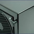
Step 5: Kickstand

To make the board stand up on a desktop, cut a piece of a large paper clip and pop it into two of the empty ground bus holes that run along the top and bottom of the board. With the paper clip on the right and the barrel jack on the left, the board stands up at about 60 degrees.
Step 6: Sketch

Download the Arduino sketch and Fritzing file from GitHub. Connect the Tempduino to a computer running the Arduino IDE with a FTDI interface and upload the sketch. The Tempduino should only be powered through the FTDI connector or the barrel jack, not both.


