

Introduction: Temperature Measurement Display on 16x2 LCD With Adjusting the Temperature Upper and Lower Limit for Warning Using Arduino
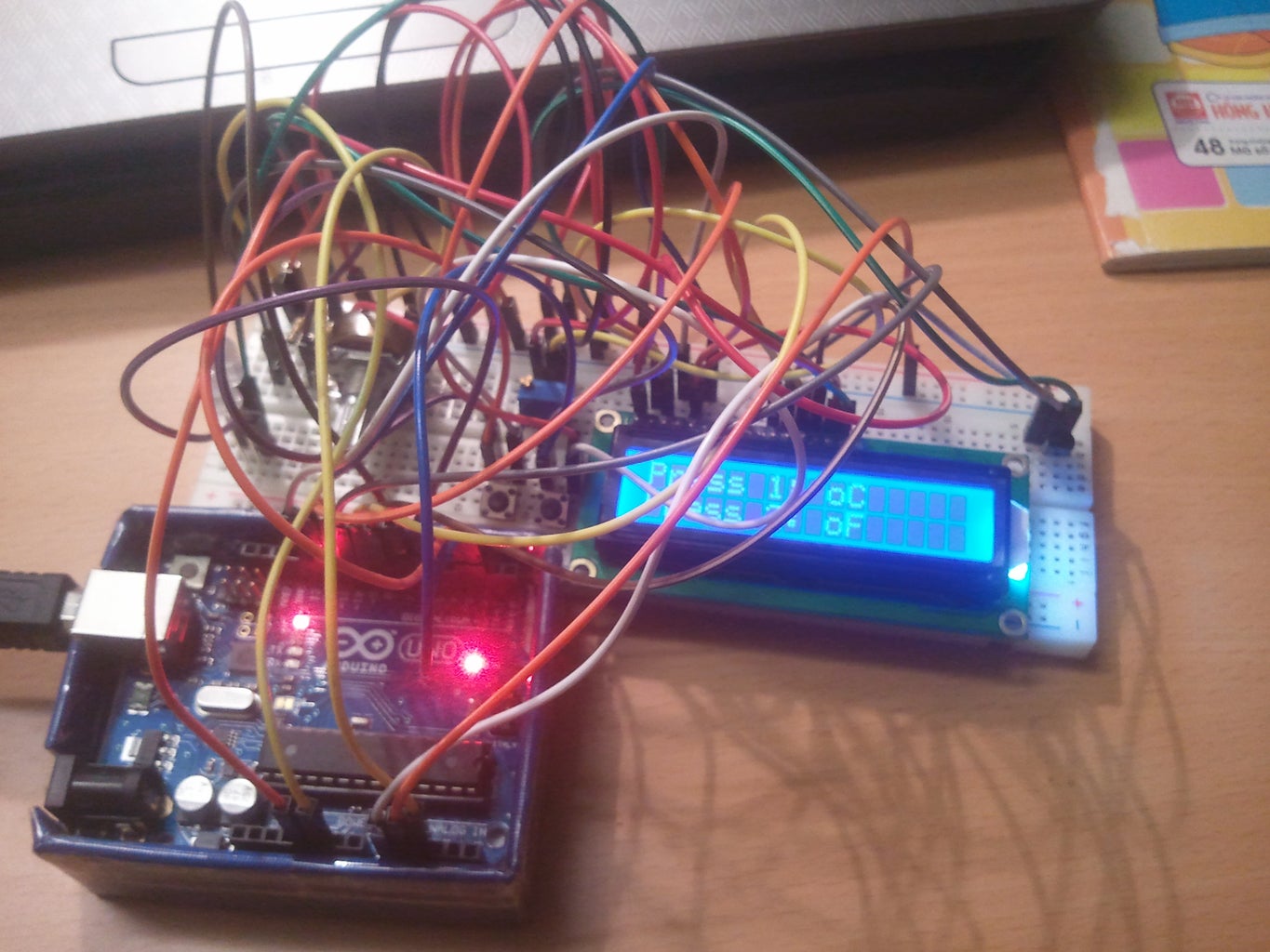
Hello everybody, here is my first project with Arduino. In this project, I will show you how to measure temperature and display it on a 16x2 LCD using Arduino , and we can use 2 button to choose what we want to see on LCD: Degrees Celsius or Fahrenheit .
I also add 2 leds into this circuit in order to warn us whenever the temperature value is lower or upper than the temperature limit we set. Leds will blink when it happens. The upper and lower limit can be adjusted with 2 resistor vars. I use LM35 sensor in this project. I won’t tell more about this sensor. We should find how to use it and see the datasheet of it.
Datasheets of LM35DZ, 16x2 LCD,…etc… can be downloaded from: http://www.alldatasheets.com/
Step 1: Material.
These are all the things we need in this project:
1x Arduino Uno (Or Nano is ok)
1x Breadboard
1x LM35DZ sensor
1x 16x2 LCD Compatible with Arduino
2x leds
2x buttons
2x 10k resistor
3x 10k Resistor Var (1 for adjusting the brightness for LCD)
Wires/jumpers
Step 2: Wire It Up


I designed this shematic and simulated it on Proteus. Let see the schematic below:
After simulating in Protues, we 'll make the real one on test board.
We’ll start with the LCD screen since it has the most pins:
Connect pins 1 and 5 to the Arduino’s GND. (Doesn’t matter which one)
Connect pin 2 to the Arduino’s +5v
Connect pin 3 to Resistor Var
Connect pin 4 to the Arduino’s Digital Pin 13
Connect pin 6 to the Arduino’s Digital Pin 12
Connect pin 11 to the Arduino’s Digital Pin 11
Connect pin 12 to the Arduino’s Digital Pin 10
Connect pin 13 to the Arduino’s Digital Pin 9
Connect pin 14 to the Arduino’s Digital Pin 8
LM35DZ sensor:
Connect pin 1 to the Arduino’s +5V
Connect pin 2 to the Arduino’s Analog Pin A0
Connect pin 3 to the Arduino’s GND
2 Resistor Var (for Adjusting Limit):
Connect pin 1 each Resistor Var to the Arduino’s +5V
Connect pin 2 each Resistor Var to the Arduino’s Analog Pin A1 and A2.
Connect pin 3 each to the Arduino’s GND
2 Mode Buttons:
Connect each button pin to the Arduino Uno’s interrupt pin 2 and 3
Connect each another button pin to each 10k Res and then connect it to the Arduino’s GND
Now we move to the last step.
Step 3: Connect and Code.

Connect the Arduino to your PC/Laptop. Download and Upload the sketch below. In case the link can’t be download, I’ve post here.
http://www.mediafire.com/download/rzd6ul71b87zwp4/Duc11_Temperature_LCD_Display_with_Adjust_Limit_GB.rar
Step 4: Make a PCB If You Want. ^^


You can make a printed circuit (PCB) like that to measure the temperature in your room or in your house…
I think it’s interesting.^^
This is my PCB:
Backward:


