

Introduction: Tetris Puzzle


A family member threw out a challenge for an education project she needed to deliver. Her idea was to create a puzzle using wooden Tetris blocks. Needing an excuse to spend more time in the garage, I set about figuring if it was possible to arrange Tetris blocks to create a completely filled rectangle. I resorted to trial and error using a 2D drawing in a 8x10 inch frame. A number of combinations I tried resulted in 3 open squares, so I created a new puzzle piece to fill the space. Other than this anomalous block type, the rest of the blocks are all true to the Tetris shapes. I did subsequently discover that this is a well known math problem with well known solutions.... you can read all about it here http://en.wikipedia.org/wiki/Tetromino - you can select your frame size to to fit a known set of tetrominos. Had I spent more time on google I could have cut down on the trial and error!
The Tetris objects are geometric shapes consisting of 4 squares with sides connected to each other on a square grid. The shapes are called Tetrominos and were made popular by the creator of the Tetris video game Alexey Pajitnov in 1984 - thank you Wikipedia..... it's time to get specific about the puzzle.
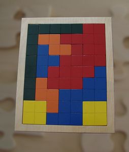
There are many ways to physically make this puzzle. You can cut the shapes out of cardboard with a pair of scissors, use a scroll saw/jig saw/fret saw to cut the tetrominos out of wood, use a 3D printer to make them out of plastic or titanium (just kidding - while 3D titanium printing is available, I expect this would be a costly option) or use a laser cutter to make the shapes out of any suitable material including stainless steel. There are many possible solutions to the puzzle which provides hours of enjoyment. Some solutions are shown in the image gallery.
I used a CNC router to cut the terominos out of 1/4" plywood. The original process was to create the shapes in Visio, export the Visio drawing as a DXF, import the DXF into CamBam, generate the tool paths for the CNC Router and use Mach3 to control the cutting of the tetrominos from a sheet of roughly 14"x14x1/4" plywood. I lost the original raw data files and access to Visio, so this Instructable is a recreation and an excuse to familiarize myself with the 123D Design tool. You do not need 3D design tools for this - a simple pencil sketch on a 1" grid will suffice. But 123D is free - free is good and 3D modelling is fun.
Step 1: 2D Trial


The first step is to create a set of tetrominos and arrange them to fill the proposed frame. I wanted the frame to be about 8x10 so I created the internal grid to be 7x9 to allow for a 1/2" border to contain the puzzle. The fact that 9x7=63 which is not divisible by 4 was completely lost on me at the time, which is why I ended up with a "3-block tetromino" for my last piece. If you adjust your frame size, you will be able to get everything to fit using standard 4-block shapes. I added an image and file that shows an 8x8 grid using only standard Tetris shapes that you can use as a basis instead.
I used OpenOffice Draw to create the 2D model. Unfortunately the app does not export a file format that the CAM software I used understands, so I recreated the 2D model in 123D.
The OpenOffice draw file is attached - NOTE: Remove the PDF extension from the file. The file you want is TetrisPlan.ODG. Instructables appears to limit uploads according to file extension.

Step 2: Model in 3D


Using 3D modelling for this is overkill unless you want to 3D print the tetrominos. The 123D Apps provide a complete tool set for modeling and production of a 3D object through connection to 3D service providers like Shapeways. There is a great summary of the process and fabrication possibilities here: http://www.123dapp.com/makeit/about
Using the 2D OpenOffice drawing as a guide, I recreated the tetrominos in 123D Design. You start with a 2D sketch (would have been great to import the OpenOffice drawing but that's not possible)and then extrude the parts to give them depth. The blocks were drawn as 1" squares on a 0.5" grid. To extrude each piece completely, hold down the control key and select all 4 squares of each tetromino and use the Press/Pull function to pull the surface up 0.25". After doing this with each tetromino (and the 3 block orphan) you should end up with a collection of 3D puzzle pieces.
You can also create a separate design file for each type of tetromino - this would be preferable for 3D printing since you can submit each file as many times as you need to get the number of tetrominos you want. If you submitted this file as is, the 3D printing company will quote you a price based on the overall volume which for this model is high because of all the space between tetrominos. I have done the design my way to simplify cutting all the parts out of a single sheet in one go with my CNC Router. This will most likely be convenient for laser cutting as well.
To compensate for the fact that a rotary cutting bit has a finite radius, the corner of each block has a 0.062" fillet operation applied. A fillet operation is just the 3D CAD terminology for applying a radius to a corner - smoothing the corners in lay speak. For laser cutting, this step is not needed but I think the blocks look better with rounded corners.
The 123D Design file is attached to get you up to speed. NOTE: Remove the PDF extension from the file. The file you want is TetrisPuzzle.123X. Instructables appears to limit uploads according to file extension.
Attachments
Step 3: Data Manipulation


With the design in 123D, you can submit directly to a 3D service (create single files for each teromino will be most cost effective), or you can submit to the 123D Make app or to the 123D CNC utility. Theoretically, submitting to the Make app will generate cut files for a laser cutter but I found it neccessary for the CNC step as well, simply because the CNC Utility crashes during the launch process. I also discovered that the online version of Make differs from the local installed app with respect to available output file formats. If you need files other than EPS output from the 123D Make web app, use the PC based app as it can additionally export the design files in DXF and PDF formats. The 123D Make PC app will not import the 123D Design file format directly so you need to export the design in STL format first, which 123D Make can import.
To summarize the steps for CNC Routing see the flowchart.
Once the design is imported into 123D Make, a custom sheet format was created to make sure that the stacked slices format only generated a single layer of plans. By defining the material thickness to be 0.25" which matches the height we used in 123D Design, we get a single layer for construction which is what we want. Click the Get Plans button and export the plans to DXF. The DXF file is imported into the CAM software (Computer aided manufacturing).

Step 4: CAM Conversion

The software I used to create the g-code is CamBam. I've downloaded a free version from the developer site which allows you to a limited number of fully functional evaluation sessions of the software (40). I think this is a great piece of software for my needs and would definitely consider buying a license for it. http://www.cambam.info/
The DXF file from the previous step is imported into CamBam. To cut a long story short, a Join operation is used to convert all the DXF line primitives to polylines, a 1" grid is drawn using polylines and each tetromino is moved onto the drawn grid. This grid is going to be engraved by the CNC so it is not just cosmetic alignment. This will make the wooden terominos appear to have been created from individual 1" blocks to mimic the video game look. Come to think of it, that is an easy construction technique - buy a bunch of 1" square wood blocks and glue them together - but then you wouldn't get to play with all the great 3D modelling tools....
The grid obscures the parts in the attached picture but the main takeaway is that we first load a 1/16" bit into the router and then engrave the grid onto the wood, and then change the bit to a 1/8" bit for cutting out the pieces. I've attached the CamBam file as well as the generated g-code. NOTE: Remove the PDF extension from the file. The file you want is CuttingPlan.cb. Instructables appears to limit uploads according to file extension.

Step 5: Making the Puzzle


Prepare the CNC Router by loading the g-code and clamping down a 1/4" 11x14 piece of plywood. The first tool I used is a special engraving bit with a 0.005" point which makes very fine lines. However, a 1/16" end mill work for this step as well. 1/8" is too thick for the grid. When the grid is complete, Mach3 will prompt for a tool change. Load a 1/8" end mill for the reminder of the program. The 1/16" end mill is too flimsy to cut the parts in a single pass. I set the Z-Axis zero position so that a few thousands of an inch of material will be left which I can cut through with a sharp knife after the CNC Router is finished. This prevents the parts from flying out which can damage the tool bit and the part, which is a total waste of your time.
That pretty much describes what you should do. The pictures show what actually happened.
1. That I forgot to do the grid - redo from scratch
2. That 1/8" end mill was too thick for the grid - redo form scratch
3. 3rd time lucky - all the parts came out great and the grid looks good
Using multiple colors of Krylon quick drying spray paint, each type of tetromino was painted a different color using my outdoor paint "booth". The "booth" is sheets of carboard spread around in a shady area of the garden. Quick drying spray paint limits the chances of insects getting embedded in the paint.
I made the frame on the fly. I machined a 0.5" thick border from 0.25" plywood followed by a solid backing board of the same outer dimensions that was glued together. And that's it. Puzzle done. I hope you find the time to build it. It makes a great gift. I would like a smaller one made out of stainless steel or brushed aluminum for a desk ornament, but that's a project for another day.

Finalist in the
Game.Life 3 Contest


