

Introduction: "The Brain" an External Hard-drive and Light Sculpture


A while back, I was asked to make a floor-standing, animated brain, external hard drive. It was to 'light up' when the hard drive was accessed and 'look good'.
When idle, it has a red, throbbing 'pulse'. When the hard-drive is accessed, it has a number of animated LED effects which make it light-up like a Christmas tree!
This Instructable gives information about the build. I made a blog about the project, but have only had one comment in two years! Hence, I thought I would give the project more exposure.
In this Instructable you can see:
- Sculpting a life-size clay brain and vacuum-forming a transparent version of it
- Installing the numerous LEDs and modifying old hard-drives to form part of the sculpture
- Creating the PIC microcontroller circuit boards which control the effects
- Building the laser-cut, illuminated 'spine'
- Building the black base and installing the real external hard-drive inside
It is not a full set of instructions to make something identical, more a set of ideas which might be of interest to others.
Step 1: Initial Concepts and Sculpting "The Brain"


Some Sketchup models were produced, so that a general idea of the project could be visualised.
Then the task of producing a clay mould to use on a vacuum-forming table was started. Full-size diagrams were printed out to show the X, Y and Z projections of the final brain. These were cut out in cardboard and the holes left in the cardboard were used as templates to get the basic shape of the clay roughly right.
Two pieces of thin MDF were sandwiched together to form an equatorial breaking line. They were cut out with a jigsaw and the clay was built up from them. In this way, a top-half of the brain was created and also a 'matching' bottom-half. A piece of threaded rod, was screwed into the bottom half and mounted on a temporary wooden base, so it would stand up properly. The top half simply rested on the bottom half.
The 'wrinkles' or 'grooves' were formed by eye with no particular basis. The only 'rule' for shaping them, was that they should not be too deep, or form shapes which would stop the brain mould from being extracted from the vacuum-formed plastic when that was done at a later stage. (A ridge is a gyrus. A groove is a sulcus. The ridges are called gyri and the crevices are called sulci).
Step 2: Vacuum Forming


I didn't have a vacuum-former, so I made one up which I used with our vacuum cleaner.
I used 1.5mm thick clear HIP sheets to make the two hemispheres. The sheet was stapled to a wooden frame. Supported in a domestic oven. Watched carefully to see it sag, tighten up and then sag again in the heat. The hot frame with the floppy plastic sheet was dropped over the mould and held on the vacuum table and the vacuum cleaner was turned on. The shape formed instantly.
Getting the mould out, was tricky - the bottom hemisphere in particular, had to be broken up to remove it (see photo in the previous step).
Each hemisphere was cut out to remove the unwanted flat plastic surround.
Step 3: Supporting the Brain


A 5mm clear acrylic sheet was used to support the two hemispheres. Essentially, the hemispheres were simply upper and lower covers for this main acrylic LED illumination platform. A surplus hard-drive was gutted to form a support at the base of the 'neck'. A plumbing fitting was used to hold a tubular acrylic 'neck' which took the whole weight of the brain. A multi-cored cable would later take the electricity from the floor-standing base up into the brain.
Step 4: Illuminating the Brain


There were two main aspects to the illumination of the brain.
1) A central, open, 'dummy' hard-drive which had 12 LEDs around the circumference of the fixed 'rotating' platter. The LEDs could be lit in sequence to simulate rotation. High brightness LEDs were also added on the end of the scanning arm which was left 'operational' because its solenoid coil was maintained and wired for use. (This 'feature' proved to be a bit of a waste of time, because the top plastic hemisphere obscured this detail.) In addition, some LEDs illuminated the underside of the platter and the underside of the 'dummy' hard-drive itself. A lot of work went into the adaptation of this hard-drive - mainly in making all of the connections invisible - the wiring was very tight!
2) 52 high-brightness leds in 6 groups were fixed to the 5mm acrylic plate which split the brain at the equator. Three groups of blue LEDs and three groups of red. Some were wired so that they could be sequenced, to show 'movement' around the equator of the brain, most were lit as complete groups. About half were sold a 'superbright' and half as 'superflux'. Most LEDs were aimed upwards and illuminated the top hemisphere, some were aimed downwards to illuminate the lower hemisphere.
The LEDs were bonded into the holes with a drop of clear glue. The LED wiring was carried out informally with very fine wire which could not be seen through the translucent hemispheres. These fine wires were led back to the centre of the acrylic sheet and were gathered together onto a piece of stripboard (Veroboard) before being connected to the main mult-strand cable which fed the LEDs from the three printed circuit boards in the pedestal below.
All of these LEDs were driven by three printed circuit boards, each having a PIC microcontroller (see later step).
Step 5: Wiring Detail


The images might look a mess, but everything was planned pretty carefully and worked perfectly!
Step 6: The Controlling Printed Circuit Boards (PCBs)


I'm a great advocate for PIC microcontrollers. They are powerful, very cheap, and easy to program. I try to keep things simple, hence the whole project used three (virtually) identical PCBs which meant that I only had to work on one design. Using three boards also meant that the PIC microcontrollers (16F88) were not asked to do too much 'clever stuff' with demanding timing and interrupts, etc.
The design was carried out using KiCad PCB software (free, multi-platform and open-source). The PIC programming was done using Great Cow Basic (don't laugh at the name - it is free, powerful and has very simple syntax. It can program a range of microcontrollers - not only PICs). I always use the PIC's in-circuit-programming (ICP) system. This means that I include a 6-pin plug on the PCB so that I can program the PIC without having to take it out of its PCB socket. This system is brilliant, allowing software tweaks to be made quickly and simply. I have a very simple serial-port programmer which lets me program the PICs directly or using the ICP system.
I start with a breadboard mock-up, just to convince myself that the basic ideas work, then produce the PCB's being careful to build in some circuit flexibility where I can.
Most of these tasks are covered in other Instructibles, but I have included some photographs and screen-dumps for interest.
Step 7: Setting Different Modes of Operation


Once installed and running, the user can tweak the configuration of the device by using jumpers on a few of the dummy hard-drive's connecting pins. Features like a 'test mode' simulating a continuous hard-drive access can be selected using these jumpers. Other tweaks include selecting which LEDs operate under different conditions and the behaviour of the lights in "the spine" - see a later step.
In addition, a press-button switch was added to simulate a disc access. When this is pressed, the unit lights up as though someone had accessed the 1Tb drive. This is a fun feature, useful for demonstrating the light display.
Step 8: Making "The Spine" - Acrylic Discs, an Acrylic Tube and More LEDs


An illuminated 'spine' like construction was to fit inside the main acrylic plinth. This was made from laser-cut transparent acrylic discs (cut locally by the very obliging "Funky Lemon" company in Ipswich UK). Each disc has three blue high-brightness LEDs embedded in it. The discs were slid onto an acrylic tube and glued on with a drop of glue. The three LEDs were connected on the disc in series and were individually wired up the spine with fine wires. A single 'common' wire ran upwards to supply the ground wire. This meant that each disc could be lit individually and a rising light effect could easily be created.
Step 9: Constructing the Base of the Plinth


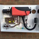
The base of the plinth contained the power supply for the electronics, the actual external hard-drive (and its power brick), a simple PCB for gathering all the wires and a fan.
The Seagate external hard-drive PCB was slightly modified to extract an electrical signal from its "hard-drive activity LED". This signal is carried up to the three microcontroller PCBs and makes the whole project light up when the hard-drive is accessed by a PC. Similarly, its USB socket is brought out to the outside. Originally, the drive was going to be a network drive, but this got changed at the last minute.
The PCB produced for the base is only there to keep things neat, otherwise the base would be a nest of random wires!
Step 10: The Plinth - a 1m High Acrylic Box


The plinth was a 'standard' 1 metre high acrylic box, more-or-less 'off-the-shelf'. In fact, I asked for three holes to be cut in the top - I did not fancy doing that task on a fairly-pricey acrylic box!
I did have to drill a couple of fixing holes at the bottom to hold the box in place on the base.
I'm fairly good at planning and looking ahead, I did have a double-take when I had to put two bolts up from the inside of the acrylic box into the base of 'the brain'. My arm was not long enough to hold the bolts and push them through - I used a long socket-set extension.
Step 11: Putting It All Together


A brief idea of the sequence of events:
When power is applied to the three boards the right-hand board starts slow pulsing of one set of red LEDs in a heart-beat pattern. This is done by using software PWM commands (part of the Great Cow Basic suite) to vary the brightness of one set of red LEDs. This code is in a continuous loop.
Depending on the configuration set by the jumpers, the other two boards do nothing, just looping round waiting for a signal indicating that the hard-drive has been accessed.
All three boards react when a signal is received to indicate that the hard-drive has been accessed. Each board doing a sequence of LED lighting effects lasting a few seconds. If the hard-drive does not get accessed again, the boards go back to their 'default' looping status. If the hard-drive continues to be accessed (this often happens) then they continue LED lighting. The first board keeps a timer going and if the hard-drive has been repeatedly access for a period of 30 seconds or more, then a 'more frenzied' set of LED lighting effects kicks in and a second signal wire communicates this state to the other two boards to let them increase the tempo of their LED effects.
The "LED effects" include:
- 'Rotating' pattern of LEDs on the dummy hard-drive platter
- 'Moving' pattern of LEDs travelling up the spine
- Random flashes of LEDs inside 'the brain'
Just for interest sake, I have reproduced the Great Cow Basic program which gets compiled and loaded up onto one PIC 16F88 to give a flavour of what the software element of this project looks like. This much more accessible than the normal PIC programming methods. Something similar is loaded onto each of the three PCB modules. Much of the code is comment, rather than active code. Anything after an apostrophe is a comment. Commenting is very important for maintaining software and this is an example of my working code - not specially commented for others to read!
'Program which drives the "Brain" board (Kicad "LED driver module 01")
' it has all of the PortB outputs connected to a ULN2804 driver ' it has PortA.4, PortA.6 and PortA.7 connected to MOSFET drivers ' it has PortA.2 (jumper 0) and PortA.3 (jumper 1)connected as mode jumpers (normally high - jumpers pull low) ' it has PortA.1 and PortA.0 as inputs ' it has no external connection to PortA.5 (pulled high and connected for Vpp)' The software consists of a 41 stage For/Next loop ' which drives the red 'heartbeat'. ' If a demand is made on the hard drive (ie PortA.0 has been driven high by the master board) ' then the blue leds on the dummy hard drive are lit alongside (ie as part of) the ' for/next loop. ' For the dummy hard drive leds to start, the for/next loop has to finish its heartbeat cycles. ' Hence there is a delay before the dummy drive lights start up.
' The software uses a software PWM (RB1)
'Program options
'Hardware settings #chip 16F88, 8 'PIC 16F88 running at 8 MHz #config MCLR = Off, osc=INTRC_IO 'Turn off MCLR, select internal osc. 'WDT and LVP are disabled automatically
'Initialise 'HEARTBEAT '~~~~~~~~~ 'Split waveform into 20 values to indicate the brightness of the red leds 'dim = 0 Bright = 60??? Table RedLedBrightness 3 3 2 2 2 2 2 10 30 50 70 90 100 100 100 100 100 100 100 100 90 80 70 60 55 50 45 40 35 30 25 20 15 10 5 5 4 4 3 3 end table
'SET PORT DIRECTIONS Dir PORTB Out
dir PORTA.4 out dir PORTA.6 out dir PORTA.7 out dir PORTA.0 in 'input line - demand being made dir PORTA.1 in 'input line dir PORTA.2 in 'mode jumper dir PORTA.3 in 'mode jumper
dir PORTA.5 in 'MCLR connected to pin A5 - not used
' next line sets up the software PWM channel #define PWM_Out1 PORTA.7
'Set initial state of port B PORTB = b'10000000'
set PORTA.4 off set PORTA.6 off set PORTA.7 off
wait 2 s ' give the programmer a moment to kick in AllLedsOff
'######################################################
'Software PWM 'PWMOut channel, duty cycle, cycles in 0.5us cycles (for an 8MHz chip) ' , 0-255 , 100 = 50us 'not convinced about the 255 value being 100% ! Using 0 - 100 seems to cover the full brightness range???
'###################################################### 'Main routine
DemandMade=false
Do
'##### Check for jumper positions '================================ modeLSB=PORTA.2 ' jumper nearest to the power block modeHSB=PORTA.3 ' jumper away from the power block mode = modeLSB+(modeHSB*2)'no jumpers = 3
'jumper A.3 in = 2 'On user instruction - referred to as "J5 in J6 out (2): High demand causes random flashing of the blue lights." 'jumper A.2 in = 1 'On user instruction - referred to as "J5 out J6 in (1): High demand is ignored. Heartbeat and dummy disc are normal, blue plate lights off."
'both jumpers in = 0 'On user instructions - referred to as "J5 in J6 in: High demand causes dummy disc, red heartbeat and blue plate lights to randomly flash." 'REMEMBER jumper positions in the user guide are numbered in reverse 'to the markings on the physical wires (wire 1 = jumper 8, etc)
'#### Check for demand and demand level '====================================== if Porta.0=on then DemandMade=true else DemandMade=false end if
if PORTA.1=on then PeakDemand=true else PeakDemand=false end if
'#### Do the code required by the jumper position '================================================ Select case mode case 3 ' no jumpers in 'PORTB is sequenced in a circle for normal demand levels and sparkles for high levels 'Red LEDs have heartbeat in all circumstances 'Other 2 outputs have random sparkling at high levels - otherwise off if DemandMade=true then PORTB = b'10000000' For cycle = 1 to 40 ReadTable RedLedBrightness, cycle, brightness PWMOut(1, brightness , 25) if DemandMade=true and PeakDemand=False then Rotate PORTB Right simple if DemandMade=true and PeakDemand=True then PORTB = random ' makes output leds 'sparkle' PORTA.4=random/128 ' just a random 0 or 1 value PORTA.6=random/128 end if next
case 1 'PORTB is sequenced in a circle for All demand levels 'Red LEDs have heartbeat in all circumstances 'Other 2 outputs are off off if DemandMade=true then PORTB = b'10000000' For cycle = 1 to 40 ReadTable RedLedBrightness, cycle, brightness PWMOut(1, brightness , 25) if DemandMade=true then Rotate PORTB Right simple next
case 2 'PORTB is sequenced in a circle for all demand levels 'Red LEDs have heartbeat in all circumstances 'Other 2 outputs have random sparkling at high levels - otherwise off if DemandMade=true then PORTB = b'10000000' For cycle = 1 to 40 ReadTable RedLedBrightness, cycle, brightness PWMOut(1, brightness , 25) if DemandMade=true then Rotate PORTB Right simple if DemandMade=true and PeakDemand=True then PORTA.4=random/128 ' just a random 0 or 1 value PORTA.6=random/128 end if next
case 0 'both jumpers in 'PORTB is sequenced in a circle for normal demand levels and sparkles for high levels 'Red LEDs have heartbeat unless there is high demand 'Other 2 outputs have random sparkling at high levels - otherwise off if DemandMade=true then PORTB = b'10000000' For cycle = 1 to 40 if DemandMade=true and PeakDemand=False then Rotate PORTB Right simple ReadTable RedLedBrightness, cycle, brightness PWMOut(1, brightness , 25) end if if DemandMade=true and PeakDemand=True then ' All ports just flash randomly 40 TIMES ' Great for MAXED-OUT brain (bright and vibrant!) PORTB = random ' makes output leds 'sparkle' if random>128 then set PORTA.4 on else set PORTA.4 off end if if random>128 then set PORTA.6 on else set PORTA.6 off end if if random>128 then set PORTA.7 on else set PORTA.7 off end if wait 40 ms end if if DemandMade=False then ReadTable RedLedBrightness, cycle, brightness PWMOut(1, brightness , 25) end if next end select
AllLedsOff
Loop '###################################################### Function AllLedsOff
PORTB = b'00000000' set PORTA.4 off set PORTA.6 off set PORTA.7 off
end function


