

Introduction: The Etchinator - Low Cost PCB Spray Etcher (under $100)


More by the author:


About: Just a guy really. Like building stuff and like to help other people build stuff too. If you really need to know, am male in my 30's and live close to Brisbane in Queensland, Australia.
What/Where/Why/How?
What is etching and what is spray etching?
Etching is the process of eating away a pattern on a target material by using an etchant liquid that attacks the target material.
The most common target materials are copper and brass. The most common etchant liquids are ferric chloride, ammonium persulphate and cupric chloride
On a hobby scale it is common to submerge the target into a container filled with the etchant. This can be very slow and is often sped up by either mechanical agitation or using an aquarium / fish-tank bubbler. Even with the speed up from sloshing the container around this process can take 10-15 minutes for a PCB or over an hour for a thick brass plate.
The spray etching method uses the same etchant liquid as the submersion method, but instead sprays the liquid onto the target. This can speed up the process by an order of magnitude.
The advantages that spray etching has over the more mundane submersion method of etching is
- Faster
- Less manually intensive
- More uniform etch
- Produces sharper edges / better detail
Where are spray etchers used?
- Manufacturing PCB (Printed Circuit Boards)
- Etching plates for intaglio printmaking
- Etching brass nameplates / plaques
- Photochemical machining of mechanical parts (often used in model trains)
- Etching jewellery
- Etching stencils (if you can't afford a laser cutter hint hint)
- Automatically generating traffic by showing friendly site logos made from brass
Why a ROTARY spray etcher?
This rotary spray etcher can be built for between $50 and $100, depending on where you need to source your material. This is a lot less than the $300 plus that other spray etching machines would cost. It is also quicker and easier to build as long as someone else has made all the errors along the way FOR you.
How?
Well here is where I get to say "follow me on this remarkable journey of discovery"
Step 1:

Background / Prior Art
Types of spray etchers
There are two main methods of building spray etch machines.
- A pressure pump and nozzles
- Rotary spray etchers that rely on centrifugal force
Pressure Pump Versions
This is the method that commercial PCB manufacturing equipment uses. In an industrial setting where reliability, throughput and lowest level of operator skill are valued over cost and size, it wins hands down.
This method is also fairly well represented in DIY projects on the web with at least three projects showing up with only a cursory search in google.
- Proto Trains design dates from 1996 but first appeared on the web in around 2002.
- Adam Seychell dates from June 2007. (Unfortunately missing in action at the moment and on the way-back machine without pictures.)
- Crreed on Instructables from Instructables dating from 2012
The commercial machines and the three DIY projects all approach the uniformity problem differently. Having some relative movement between the nozzle and target removes problems with high pressure spots. Having the target in a horizontal orientation reduces undercut.
| Nozzle | Target |
Target Orientation | |
| Industrial | Stationary | Moving | Horizontal |
| Proto Trains | Stationary | Moving (rotating) | Vertical |
| Adam Seychell | Moving | Stationary | Horizontal |
| Ccreed | Stationary | Stationary | Vertical |
Rotary Spray Nozzle Versions
Rotary spray etchers are a whole different kettle of fish when it comes to DIY projects. It seems that although newsgroups are littered with people starting a project to build one, only one DIY project seems to have been published on the web to look at. It is also not the easiest thing to find as it is in German and “spray etcher” will not turn it up in a google search.
Spruhatzanlage use google translate or BableFish to make a bit more sense of it
The German site although very professionally done and full of helpful pictures, does not address the pitfalls of building one yourself.
Pressure Pump Vs Rotary
Pressure Pump
Pros
- Can be scaled up
- Can be built with target in horizontal position (reduces undercut)
- Can achieve higher uniformity of etch if either target or nozzle are moving
Cons
- Expensive to build (relative to rotary)
- Difficult to find suitable pumps (Seychell recomends against Shurflo)
- Labour intensive to build (relative to rotary)
- Poor uniformity with static nozzle/target
- Risk of hoses coming loose and coating your workshop in etchant with some Spray Etcher designs
Rotary Spray
Pros
- Cheap to build
- Easy to build
- Excellent uniformity over a small area
- Lower risk of accidents spraying etchant around
Cons
- Can not be scaled up in size a great deal
- Target can only be vertical
- very difficult to get working well (until now)
Step 2:


Materials and tools
You are going to be using knives, saws, power drills and solvent glues here. Take all the usual safety precautions. Wear goggles where appropriate. Work in a well ventilated space. Follow all the safety precautions on what ever etchant liquid you end up using.
Also a note on measurement and dimensioning. I assume anyone interested in building a spray etcher is familiar with metric no matter where in the world they live. So all of my dimensions are metric. I have included imperial measurements only on parts that are of general interest (such as the diameter of the motors). Also I have not included solid dimensioning as the exact crate I used is unlikely to be available outside of Australia.
Materials (Basic Version)
| Item | Cost | Notes |
| 2 Motors | $6.00 | Surplus $3 each. Motors for my first unit where $12 each locally. |
| Small HDPE crate | $9.00 | Starmaid/Rubbermaid whatever. Mine was “icon” brand. |
| 20mm PVC conduit | $3.00 | Need approx 500mm. Actual OD is 27mm. |
| 50mm PVC conduit | $4.00 | Need approx 200mm. Actual OD is 58mm. |
| 25mm PVC round | <$1.00 | From Reverse Garbage which is a local surplus/salvage shop. Most localities should have similar scrap. |
| 5mm rigid PVC | $15.00 | Small amounts should be able to be scrounged saving $15. |
| 2 ABS toy car wheels | $4.00 | Any hobby shop. |
| 2 Plastruct extrusions | $10.00 | I used 1/4” angle but anything about that size is OK. |
| Cushion foam off cut | $4.00 | 20mm thick low density foam off cut from Clarke Rubber a local foam rubber vendor. |
Materials (Deluxe Version)
| Item | Cost | Notes |
| Motor controller | $9.00 | Subject of separate instructable. |
| 2nd HDPE crate | $9.00 | To hold hot water to both warm etchant and rinse spray wands. |
Sundries
| Item | Notes |
| PVC Cement | Any glue that will work on PVC and ABS |
| Double Sided Tape | |
| Power Supply For motors | |
| Scrap brass or steel round | Slightly larger than your motor output shaft |
Tools
| Item | Notes |
| Small lathe | Sorry about this but you will have to beg borrow or steal one. |
| Drill Press | Hand holding a Dremel will not cut it for the spray holes. |
| Fractional drills | You may be lucky with your motor shaft being a non-fraction size. |
| 0.6mm drill | For spray holes. |
| Tapered hand reamer | |
| Saw and mitre box | I use a power saw in some shots but a hand saw will work. |
| Small vice | |
| Bench Vise | |
| Rulers | |
| Tri square | |
| Set of files | |
| Marking pens | |
| Compass | To draw circles and to mark out. |
| Pair of scissors |
Optional Tools
| Item | Notes |
| Dremel | Makes cutting slots easier. |
| Circular power saw | Makes cutting rigid PVC much faster. |
| Set of hole saws | Will avoid some chain drilling and filing. |
| Optical tachometer | To measure spray wand speed. |
Saving money and getting PVC
The two most expensive items in the materials list are PVC and Plastruct extrustions.
These items could easily be made into $0 items from scrounging and making.
I purchased all the rigid PVC sheet I needed for my builds, as I knew I would be making several units to test and perfect. However, rigid PVC is very common and off cuts should be available for little or no cost.
The Plastruct extrusions are not critical in either size or shape. The reason for using the expensive plastic from a hobby shop was just for convenience. The spray wands would be perfectly functional if you substituted a 5x5mm strip cut from the edge of the rigid PVC. This however is not an easy ask unless you have a table saw or at minimum a circular power saw.
The photo above shows a PVC strip cut with a power saw next to the Plastruct. It is quite difficult to cut thin strips like this with a hand saw. A power saw or better still a bench saw with a fine blade makes this fairly easy. If you have neither then the $10 for the Plastruct is a good investment in your own sanity.
Step 3:

Exploded view
Less of a step in construction than a photo to hopefully make the later steps less confusing.
As you can see there is not much to the spray etcher.
If you had access to a CNC router or a laser cutter the whole thing could go together in a few hours. Even if you have limited tools like me and have to chain drill and file everything, the whole project can be completed in well under a day.
Step 4:


Selecting your crate
This is where your first design trade off comes in. Too small a crate and the angle between the spray wands and target will be large and uniformity will suffer. Too large a box and you will have a very large liquid volume to fill up.
The liquid in the bottom of the tank/crate needs to be about 25mm (1”) deep. The tank I chose was quite small at 240 W x 300 D x 260 H. So the total volume of etchant I need to make 25mm depth is
240 x 330 x 25 / 10^6 = 1.98 litres (0.5 gallon)
Having the angle the spray hits the target much greater than 25 degrees will adversely effect etch uniformity. This is not important if you are only aiming for 10/10 thou PCBs, but if you are looking to get 6/6 or 4/4 results then you need to pay attention.
The spray wands need to be set in at least 20mm from the corners of the box. This will give you your distance from spray want to target. In my case the distance from wand to target was 140mm.
My standard sized PCB is 75 x 150mm so that gives me 37.5mm off axis for the edges of the PCB.
Tan-1 (37.5 / 140) = 15 º
well within the 25 º limit.
One other thing to look for in the tank is a lip inside for a false lid. The false lid is needed to stop spray from reaching the interface between the lid and the crate.
If your tank does not have a lip, you will need to glue in some rails to hold the false lid.
Step 5:

Selecting Motors
With the 20mm (26 actual) diameter spray tube, to get a uniform etch top to bottom your motor has to run about 3000 RPM. Higher RPM will lead to the top of the target being etched more, lower RPM will lead to the bottom of the target being over etched.
However this speed will change depending on spray hole diameter and spray tube diameter.
If you stray from the listed 26mm OD tube and 0.6mm holes then you will have to experiment to find your own sweet spot in the RPM. However unless you are aiming for 4/4 rules on a PCB then this is not critical. I can run anywhere between 2600 and 3400 RPM and get excellent result.
The power requirements of the motor are fairly modest. In my set up when running at the optimal 3000 or so RPM the motors are pulling about 9 watts each.
Ideal place to find motors.
An ideal motor is probably going to be a 5 pole motor around 40-45mm x 60-70mm (1 3/4 x 2 1/2 ") . This is around the size of an RS750 / RS755. These are the kind of motors that are often used in larger cordless power drills.
The surplus motors I am using at present are no longer available. I am currently sourcing several different surplus motors with good availability to test them.
I will update this instructable when I have a good source to link too.
Step 6:


Cutting Motor Holder, false lid and false bottom
For all the steps in making the false bottom, false lid, lid and motor holder accuracy and symmetry are very important. If the holes and slots don't line up, then the tubes will foul and rub. There are a few tricks and tips along the way to make this easier. There is however no substitute for being careful with your ruler and tri-sqaure.
First measure up the crate at the point where the false lid and false bottom will go. The false bottom should be 25mm from the actual bottom of the crate. The false lid will be at whatever height the lip inside the crate is. If your crate has no lip then measure the false lid at a point 25mm below the real lid.
Cut out the 3 sheets of PVC.
Measure and mark out the radius on the corners of the false bottom and false lid.
Mark out any intrusions or cut outs needed.
Cut, Chain drill and file
You should now have the three pieces of PVC the right shape to test fit in the tank.
Step 7:


Cutting slots and large holes in PVC
As stated previously symmetry is paramount. So measure the size difference between the motor holder and false lid. Then mark out half that distance on the back of the motor holder with a pen. Finally use the pen to trace all the way around the false lid.
Repeat the same procedure between the false lid and the false bottom. You will now have pen outlines to help you line up the parts.
Use double sided sticky tape to attach the three PVC parts. Your pen outlines just drawn should make it easy to line up the parts as you are sticking them together. This sandwich of PVC will make all further cutting line up perfectly.
Mark out the circle that is going to be cut through all three parts to accommodate the spray tubes. The edge of the tube should be somewhere around 20mm from the edge of the crate. The hole should be around 5mm larger than the spray tube itself.
Use the 0.6mm drill to drill a hole through all three sheets at the centre of the circle. When you turn the PCV sandwich over to the top side, you now have reference points to mark out the slot.
Turn over the PVC sheets so now you can mark out the slot on the top side of the motor holder. The slot is only cut through the top two PVC sheets. However you must mark it out before you cut the tube holes through all three sheets or you will loose your reference points.
Follow diagram 8.1 to mark out the slot perpendicular to the spray tubes.
- Use a ruler to draw a line between your two reference points (0.6mm holes)
- Measure the half way point between the two reference points
- Use your compass to mark two arcs along the line from the centre point
- Approx double the distance on your compass and draw the two sets of arcs using the intersection of the first arcs and the centre line as the new centre point
- Draw a line between the intersection of these two sets of arcs.
You now have a perpendicular line to mark out your slot from.
Chain drill and file the tube holes through all three sheets of PVC
Remove the false bottom and chain drill and file the slot in the false lid and motor holder.
You now have the three sheets of PVC as shown.
Step 8:


Attaching motor holder tubes
Cut two lengths of the 50/58mm PVC pipe to about 25mm (1”) longer than your motors are.
Use a ruler and your marking pen to make 4 points to line up the tube with the hole. You can not use the marking pen to trace the position here as the solvent glue will wash it away.
Use a knife to trace a scratch into the surface of the PCV to mark the position to glue the tube too.
When the PVC solvent is painted on the surface this faint scratch will become a lot more visible.
Apply the glue to the PVC pipe and attach to the sheet of PVC using your traced scratch as a guide.
The motor holder is now complete.
Step 9:


Cutting holes and slot in real lid and attaching motor holder
Put the false lid inside the crate and put the real lid on top of the crate.
Using your eye mark out with a knife the location of the slot and holes. As you have to mark these out by eye, it is probably a good idea to make them a few mm over sized.
Chain drill and file as per previous slots/holes.
Put the real lid back on the crate.
Apply double sided tape to the real lid
Line up the motor holder with the false lid below and attach to the real lid.
Step 10:


Adding the stator fins to the false bottom
Cut out several 25mm tall rectangles from scrap PVC.
Make sure you file at least one edge flat to provide a good mating surface for the glue.
Glue them to the bottom of the false bottom as shown.
Step 11:

The complete crate / tank
One third of the way there.
The complete tank with false bottom, false lid and motor holder.
Just a couple of spray tubes and a target holder from the complete Etchinator.
Sit back and admire your work so far.
Step 12:


Motor Couplers
Cut three lengths of the PVC round. Size is not too critical. I cut mine around 25mm (1”). The only important thing is that it is longer than the hole you are going to drill for the motor shaft. The third length is not going to be used in the final tubes. It is only for test drilling and therefore size does not matter at all.
Use the third scrap piece of PVC and drill several sized holes in it (mark each size so you don't forget). Push fit the motor shaft into the holes. The smallest hole that you can just push the motor onto is what you will use. In my case it was 4.9mm which was 0.1mm smaller than the shaft.
Mark the centre of the two PCV rounds and mount in your small vice. Drill the hole for the motor shaft.
Get your scrap piece of brass and mount it in the chuck on the lathe. Turn it down to the same size as the motor shaft (possibly 0.05mm smaller). This is now going to be your mandrel to machine the motor coupler to its final size on.
Mount the PVC round on this mandrel.
Turn down the PVC taking of a few 10ths of a mm each pass. You will notice how badly off axis and off centre your drill hole is now (even though you thought you where doing such a good job).
As you are approaching the final size start taking lighter cuts and try test fitting a scrap from the spray tube. It should be a light interference fit.
Step 13:


Impeller
Make another brass mandrel for mounting the plastic wheel in the lathe.
Mount the wheel with the outside facing towards the tailstock.
Turn down the outside diameter to be the same as the OD on the spray tube.
Face the end of the wheel to get rid of the bumps.
Turn the wheel around on the mandrel so it is facing the other way.
The webs inside the wheel are the impellers radial fins. These need to be turned down to fit inside the spray tube. The fit on this is less critical than the motor coupler and a bit undersized is acceptable.
After the wheel has been turned down , you need to make the hole up the Centre. Use your tapered reamer trying hard to keep the hole in the centre of the impeller.
Step 14:


Cutting and drilling the spray tube
Measure the height from bottom of the motor coupling to about 10-15mm (1/2”) below the false bottom. This is the length to cut the motor tube.
You have to mark out 3 lines 120 degrees apart. Using a protractor to do this without having a centre point is difficult. An alternative is to measure the circumference and divide by three.
Put a mark on the end of the tube with your pen. Then lay the tube down on top of a ruler with the mark at the zero point. Carefully roll the tube along the ruler till the mark reaches bottom dead centre again. Read the point on the ruler to get your circumference. Divide this number by three and roll the tube along the ruler again marking off the 120º and 240º points.
Clamp your pen in the small vise so the point of the pen is perpendicular to the edge of the tube. Carefully hold the tube stationary. Slide the vise along the bench keeping the point in contact with the tube.
Mark the drill points at 6mm intervals along the first line. Mark the second line with the same 6mm intervals but vertically offset by 2mm. Finally do the marking of the third line offset vertically by another 2mm (4mm total offset from the first points).
Carefully drill all 200 or so holes in the two tubes.
Cut six lengths of plastruct (or PVC strips) about 25mm shorter than the tubes. These are the dams to keep water above the spray holes.
Test fit the dams so they are on the downstream side of the holes. You will have to hook up your motors and work out their preferred direction of rotation. If your motors are bidirectional then either side as long as all 6 are consistent.
Mark the position to glue the dams. Very carefully glue the dams making sure not to drip any glue that will block spray holes. The reason for drilling the holes first and risk blocking is so you can look down the middle of the tube and have a reference for gluing the dams in straight.
You now have the motor coupler, tube and impeller all ready to assemble.
Step 15:


Gluing together the pipe and keeping it in round
Gluing the spray tube to the motor coupler is probably the most critical part of the build. If this is done badly then all the other effort in keeping things straight and true is wasted.
This is where the large bench vise comes in for a little trick in keeping the tube in round.
If you mount the motor in the bench vise and arrange it so the bottom of the tube is close to the bench. You can then slowly turn the motor by hand. As the motor turns you will be able to see the small gap between the bench and the end of the tube change.
The first two photos in this step show a very exaggerated out of round condition.
Adjust the tube so it is closer to being in round. Adjust the motor in the vise jaws to bring the end of the tube close to the table again. Repeat the process of turning the motor by hand and adjusting the tube. Keep repeating this process until there is no more than ¼ of a mm wobble at the end of the tube. Preferably you should be looking at less than 1/10mm.
When you have got the tube attached, you can then glue the impeller in the end.
Measure up the motor for the foam ring around the outside. Cut the foam. Attach double sided tape to the motor and push the motor and foam into the motor holder tube.
Step 16:


The target / PCB holder
By now you should be pretty good at cutting out, filing and glueing PVC. So I won't go into too much detail on that.
The part of this step that needs a bit of explaining is cutting the groove that the PCB rests in on the side of the holders arms.
First snap a few blades off the end of a large box cutter blade. Mount this in the end of the small bench vise so that 2.5mm (½ the width of the PVC) protrudes. This device is going to be used like a plane to shave a groove into the PVC.
Use some double sided tape to mount one of the PCB holder arms to the edge of your bench.
Now pressing the top face of the vise against the side of the arm, run the blade back and forth with light downward pressure. The two large photos clearly show what I mean here.
As you gain a bit of confidence you can increase the downward pressure to make deeper cuts/shaves. Be careful not to press down too hard or the blade may come loose. With a bit of practice and skill you can cut one side of the groove with about 30 strokes back and forth in around one minute.
Unmount the arm from the double sided tape, turn it around 180 degrees and cut the other side of the groove.
The PCB holder arm will now have a V groove in as shown underneath the ruler.
The final step for the arm is to file a notch 5 or 10mm up from the bottom. The square edge on this filed notch is what stops the PCB from sliding out the bottom of the holder.
Repeat the grooving process for the second arm.
The next photo shows the two arms, the two wings/flanges, a set of M5 wing nuts and bolts and two optional square pieces of PVC to hold the head of the bolt captive.
Finally a shot of the the bolt holder close up and the whole assembly glued together.
Step 17:

Gratuitous Action Shot
The Etchinator is now complete.
All that remains is to hook up a power supply, add 2 litres of water and fire her up for a test.
When turning on the unit it is good to start the motors just spinning slowly around 200 to 400 RPM. This will aid them in “picking up” the liquid. Once they have been running slowly for 5 seconds, you then increase the motors to running speed.
This start up procedure is automated by The Etchinator Controller that is detailed in a separate document.
In use it is helpful if you have budgeted the extra $10 for a second crate. Five minutes prior to etching you can pour 2 litres of hot water into the second crate and then put the crate containing the etchant inside the hot water crate.
This will heat the etchant and improve speed and etch quality.
Also after etching is complete you take the etch tank out of the second tank. You can then lift the entire lid, spray tubes, PCB and PCB holder off the etch tank and onto the tank containing clean hot water. Then run the motors for a little while and you have cleaned up everything ready to pack up in a few easy steps.
The uncut complete lid from the second crate can then be used on the etch tank and the etchant can be stored in the tank as only HDPE and PVC are used. Both of these plastics are safe long term for both FeCl3 and CuCl.
Step 18:


Results
Hopefully the results speak for themselves.
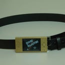
The Instructables robot here shows great uniformity in the relief etched areas, The etch depth/width ratio in the areas such as the fingers and wheels is excellent. The brass the robot is made from is 0.7mm thick. The depth of etch is 0.35mm and the undercut is only around 0.05mm.
Total cost of the first V1.0 unit I built was probably $90
Total cost of making duplicate units now is around $50
It wasn't all smooth sailing though. The total cost to get this far in design was probably several years and many $100 of dollars. In the next few appendix steps I will detail a few of the things you should NOT do or try.
If this project is well received and people seem keen I have another few projects about home brew PCB manufacturing equipment
- Laser Photo plotter for under $100
- CNC PCB drill
- PCB through hole plating tanks
- Laminating multi layer PCBs
Step 19:


Appendix A - Random uneven etching and its solution
The photo of the PCB in this step is showing a stripe that is >5mm wide that is under etched.
After 90 seconds of etching the copper on the entire rest of the PCB was removed. Only this wide stripe and another just above it were not completely etched. The machine was run for a further 30 seconds before being stopped. The >5mm wide strip still showed no signs of breaking through with an additional 33% longer in the machine.
The cause of this stripe can be clearly seen in the side on photo of the spray pattern.
Early on in my spray etcher building adventures I was using a hand drill to drill the spray holes.
Just a tiny angular variation from perpendicular can cause quite large gaps in the spray coverage. This inaccuracy manifests itself in two problems. As the first figure shows, not only does the gap leave an under etched area, but the section next to the gap will be over etched.
A second type of inaccuracy in drilling is being off axis radially. The second figure in this step shows that problem.
The two normally drilled holes will function well by forcing out liquid as the tube spins. The Third hole, however will be trying to force liquid back into the tube rather than out of the tube.
This error has to be much worse before it results in uneven etching. The second photo shows the pattern from a spray tube looking down from the top. This spray pattern has a fairly large variance and no unevenness in etching could be detected from this tube. You almost have to try and do a bad job of radial alignment before it becomes a problem.
The solution to the first problem also completely eliminates the second problem – Make sure you use a drill press and hold the tube in a vise or against a fence.
Step 20:


Appendix B - Patterned uneven etching and its solution
The first photo of a PCB in this step shows a small amount of copper left in stripes 6mm apart. This etch was stopped at 90 seconds. Most of the copper on these stripes had been removed and maybe another 10 seconds would have completely cleared the board. So this issue is a lot less dramatic than the first problem.
If you are only making PCBs and are only aiming for 8/8 rules then this problem is of no concern to you.
If you are aiming for 4/4 or you are etching thick brass then then next three photos in the series show this problem in a worse light.
One of the photos is a small section of brass front on. You can clearly see a pattern on the face of the brass.
The next photo is the same piece of brass side on. Still not very dramatic.
The main photo in this step is the same side on shot. In this image the contrast has been turned right up and you can quite clearly see how bad the wavy pattern is in the depth of the etch.
The cause of this 6mm banding is actually the tube being out alignment axially.
Figure one in this step shows how the liquid in the centre of the tube will pool on one side if the tube is out of axial alignment.
A partial solution to this problem is the dams on the inside walls of the tubes as shown in figure 2.
The dams can only bring a slightly misaligned tube back to being uniform. It is still very important to be as accurate as possible when gluing the tube onto the motor coupler.
Step 21:

Appendix C - Poor start up performance / pressure loss and its solution
Five years ago when I began building my first spray etcher there was a lot of discussion on the homebrew PCB newsgroup about rotary spray etchers.
One particular thread was about how the rotary spray tube should work with simply a hole in the bottom that is smaller than the inner diameter of the spray tube.
I won't detail all of that discussion here as you can find it via google if you are keen.
I did take on board the idea and some of the early tubes I tried simply were a hole drilled in the bottom of a PCV pipe end cap. A photo of one of these early efforts is shown.
Sometimes these tubes would work flawlessly and sometimes they would fail to start up.
Attempting to solve this problem I tried small axial fans at the inflow hole. This improved the start up performance quite a lot. The axial fan had another problem though. At higher speeds the tube would start spraying less water. This would unload the motor and cause it to spin even faster. This positive loop would eventually lead to a very over speed motor and no spray at all.
Even if you monitored the speed of the motor, the axial fan version would gradually spray less and less liquid as the time went on. The only fix was to stop the motor and restart it. This problem was not critical when etching a PCB that would only take 60 to 90 seconds. But a thick sheet of brass that could take up to 25 minutes to etch would always fall foul of this problem.
The final design here has a radial fan/impeller after the inflow hole. Although not quite the best solution I have found, it is able to be constructed without a five axis CNC router.
The radial impeller design here has two drawbacks. Firstly it must begin at low speed and sped up gradually to ensure start up. This problem is trivial to over come. Either slowly dial up the voltage on the PSU running the motors or it can be taken care of with a microcontroller that is also used to automatically stop the etcher after a pre set time.
The second problem occurs if a whirlpool/vortex forms underneath the tube and the fan sucks in air. This can cause the tube to completely loose pressure/stop spraying. The solution to this problem is the false bottom on the tank with the stator fins.
The false bottom and stator fins disrupt the swirl of water and prevent a whirlpool from forming deep enough for air to be ingested by the impeller.
Step 22:
Results
(Repeat of step 18 for those people that only read step 1 and step n)Hopefully the results speak for themselves.
The Instructables robot here shows great uniformity in the relief etched areas, The etch depth/width ratio in the areas such as the fingers and wheels is excellent. The brass the robot is made from is 0.7mm thick. The depth of etch is 0.35mm and the undercut is only around 0.05mm.
Total cost of the first V1.0 unit I built was probably $90
Total cost of making duplicate units now is around $50
It wasn't all smooth sailing though. The total cost to get this far in design was probably several years and many $100 of dollars. In the next few appendix steps I will detail a few of the things you should NOT do or try.
If this project is well received and people seem keen I have another few projects about home brew PCB manufacturing equipment
- Laser Photo plotter for under $100
- CNC PCB drill
- PCB through hole plating tanks
- Laminating multi layer PCBs

Finalist in the
Hurricane Lasers Contest


