

Introduction: A Compact, Arduino Altimeter for RC Planes
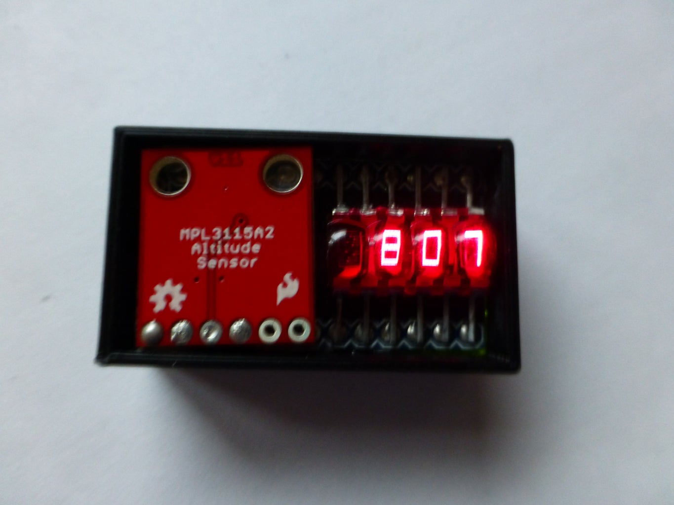


The Ultimate Altimeter is a super-compact, Arduino controlled altimeter capable of measuring the altitude with an accuracy of 0.3 meters, and saving the highest and lowest values it has measured. It is powered by a 40 mAh Lithium Polymer battery, uses a tiny LCD Bubble Display, and measures altitude with a MPL3115A2 Altitude Sensor. It's very simple and fairly easy to build with just six major components. Additionally, an optional 3D printed case can house the Altimeter.
The Altimeter has a couple of different modes: current altitude, highest altitude, lowest altitude, difference in altitude (highest minus lowest), and standby (turns display off to save power for ~6 hr battery life, not shown in video).
The entire build adds up to around $30, but you may have some or most of the parts lying around already.
You can make this! It is not a very difficult project, and could be good practice for through-hole soldering, and coding (if you want to do modifications). Read on and create!
Step 1: Materials List
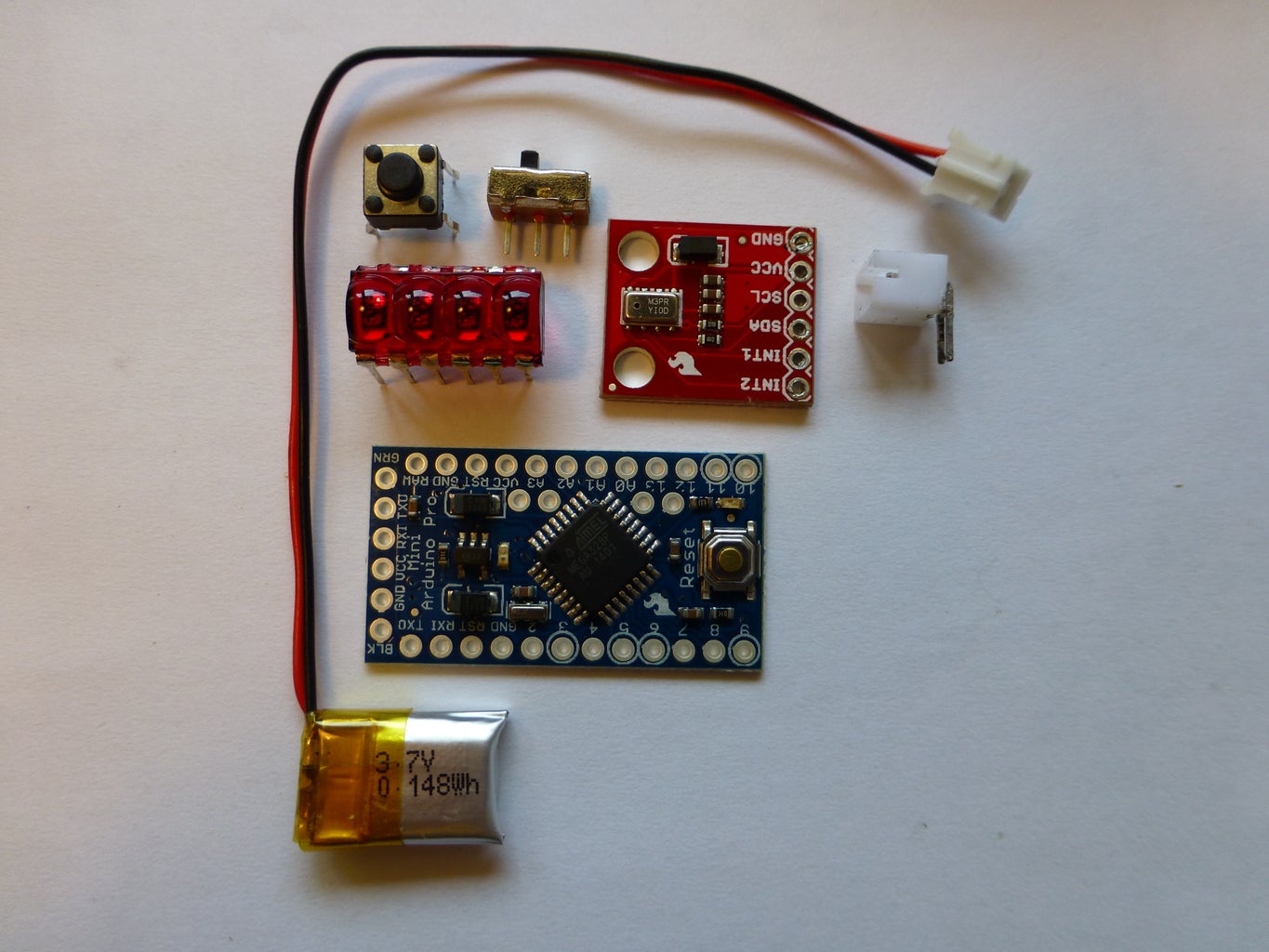
Parts:
Tools and other materials:
Soldering iron
Solder
Flush cutters or wire cutters
Wire strippers
Electrical tape
Liquid electrical tape or other insulative paint (you could also use regular electrical tape or heat shrink tubing)
24 guage stranded wire
Hot glue gun
Step 2: Solder the Bubble Display


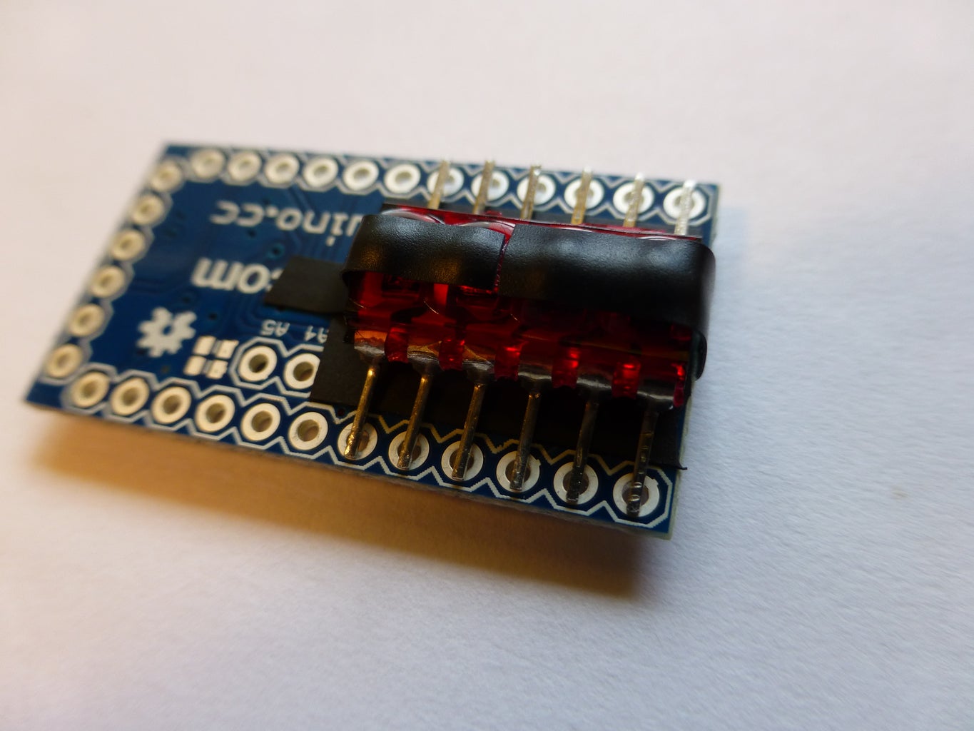

The Bubble Displays are set up to be put into a breadboard, but since we will be soldering it directly onto the pins on the back of our Arduino, the leads need to be bent flat with a pair of pliers. Once bent, rest the display on a flat surface, and make sure it lays flat and all of its leads touch the surface. This will ensure that they will make good contact with the pins on the Arduino.
Next, put down a piece of electrical tape as shown in order to prevent unwanted connections between the board and the display.
Temporarily tape the display down to the Arduino in order to keep it in place while you solder the leads to the corresponding pins on the Arduino. The leads don't actually go through the holes; they can just rest on top and be connected with solder.
Step 3: Add the Button


Bend out two of the adjacent leads on the button and snip them off. Then solder the remaining leads to GND and PIN 3 on the Arduino.
You can trim the button shaft to the length of your liking. If you a snipping device, the shaft will break uncleanly. I used a thin saw to cut it, and then filed it smooth.
Step 4: Add the JST Connector and Switch


IMPORTANT:Read this whole step before starting it. It is put together strangely because I had to change and fix the project as I built it. Also, there are some things in the photos that haven't been covered yet because the order in which I built it is different from the order of this Instructable.
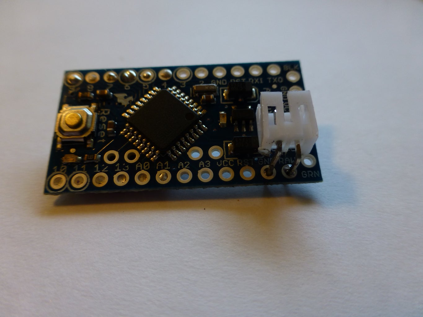
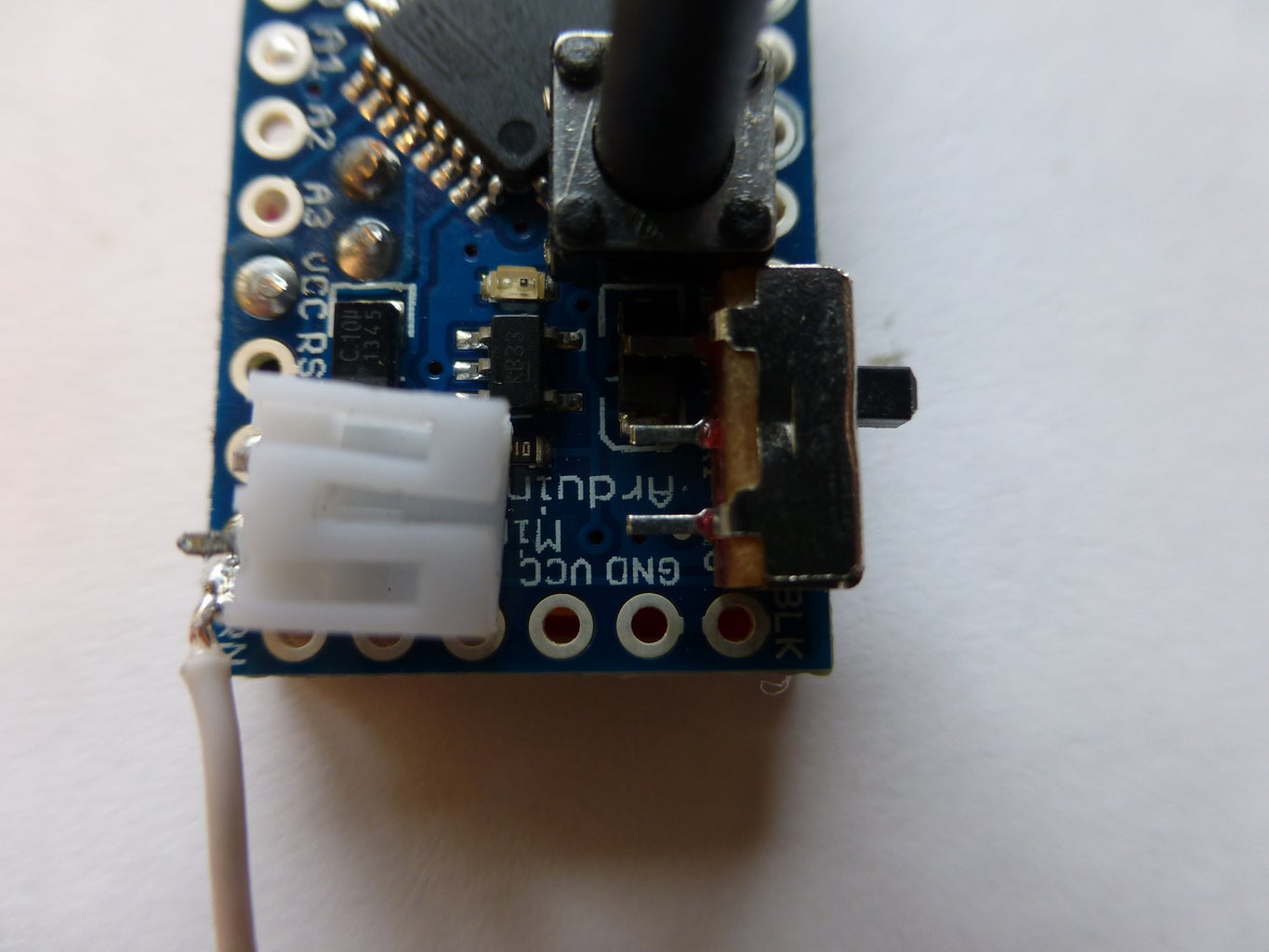
Solder the JST connector into the GND and RAW pins on the Arduino. Then, cut the lead that goes to RAW in half. This is where the switch circuit will be added so we can turn the device on and off
Glue the switch into place. Push it right up against the button so there is enough space to program the Arduino with FTDI later. I used superglue to stick it in place. We won't be using any of the pins that it is covering up so you can glue it right onto the board.
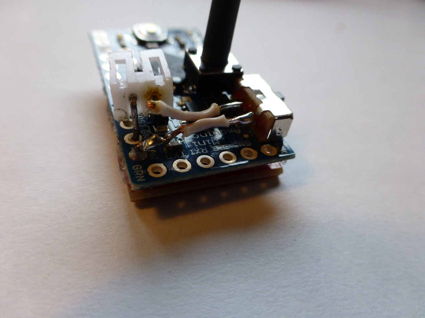
Next, twist the JST connector so it is facing the rest of the board instead of the switch. This will allow the battery to plug in (there wasn't enough space before). Only one of the leads of the connector is in the Arduino now, so it should be easy to twist. You may need to do some supergluing to get the metal pins that stick into the plastic part of the JST connector to stay in place.
Solder the button into the cut lead of the JST connector as shown in the picture, and you are done with the power circuit!
Step 5: Connect the Altitude Sensor
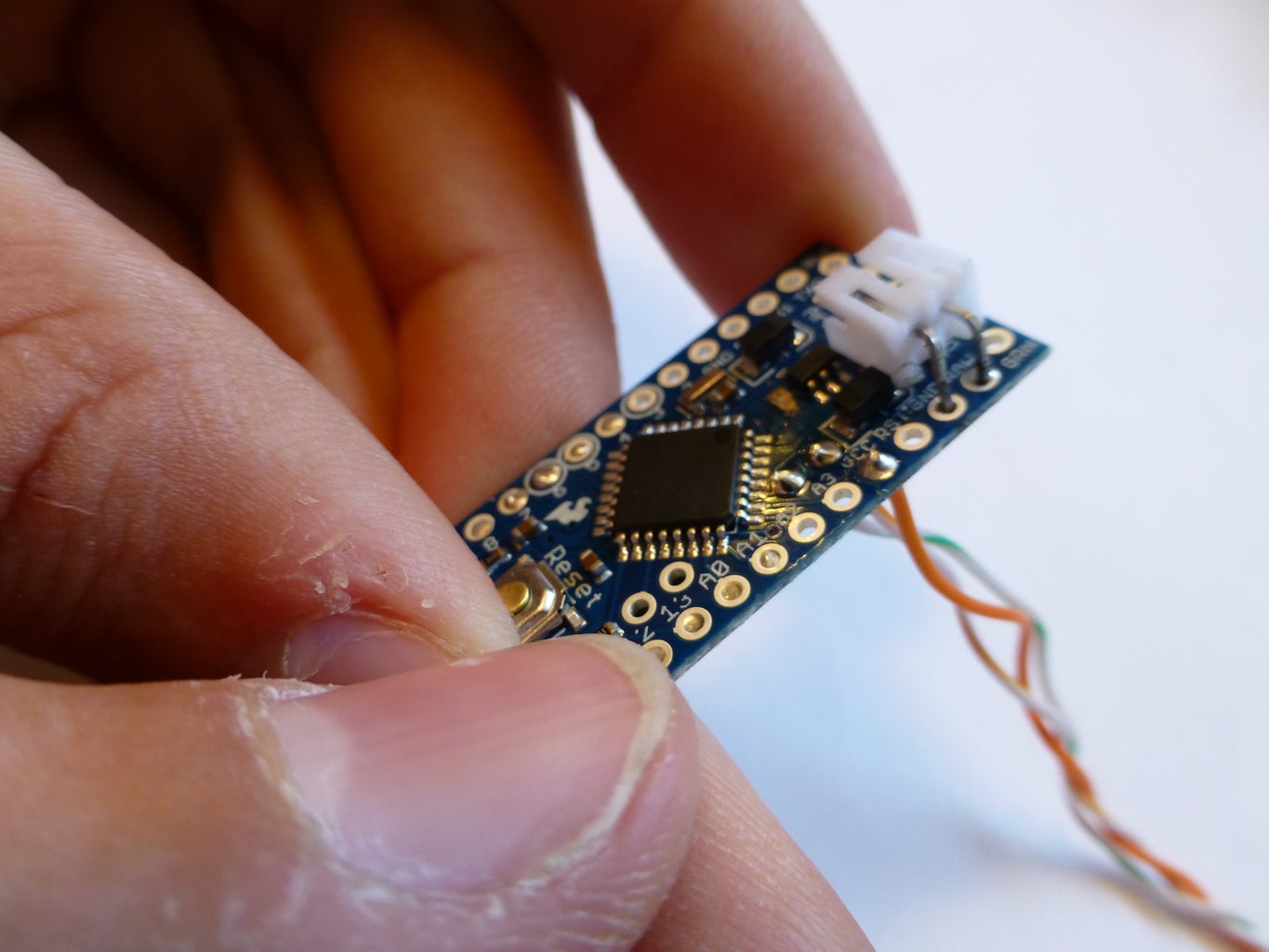


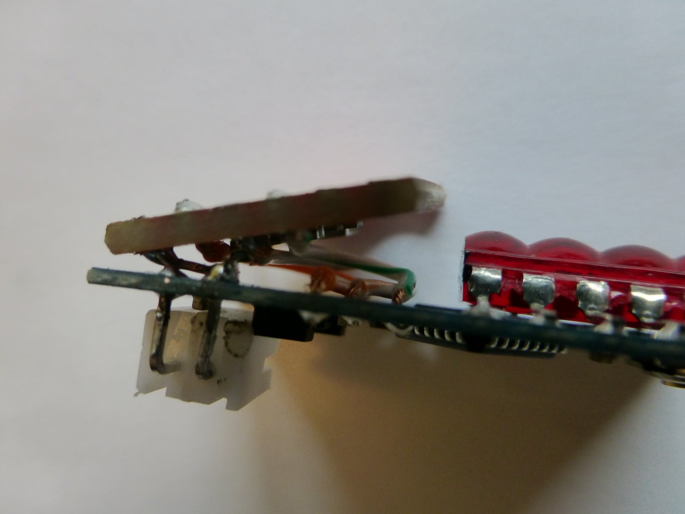
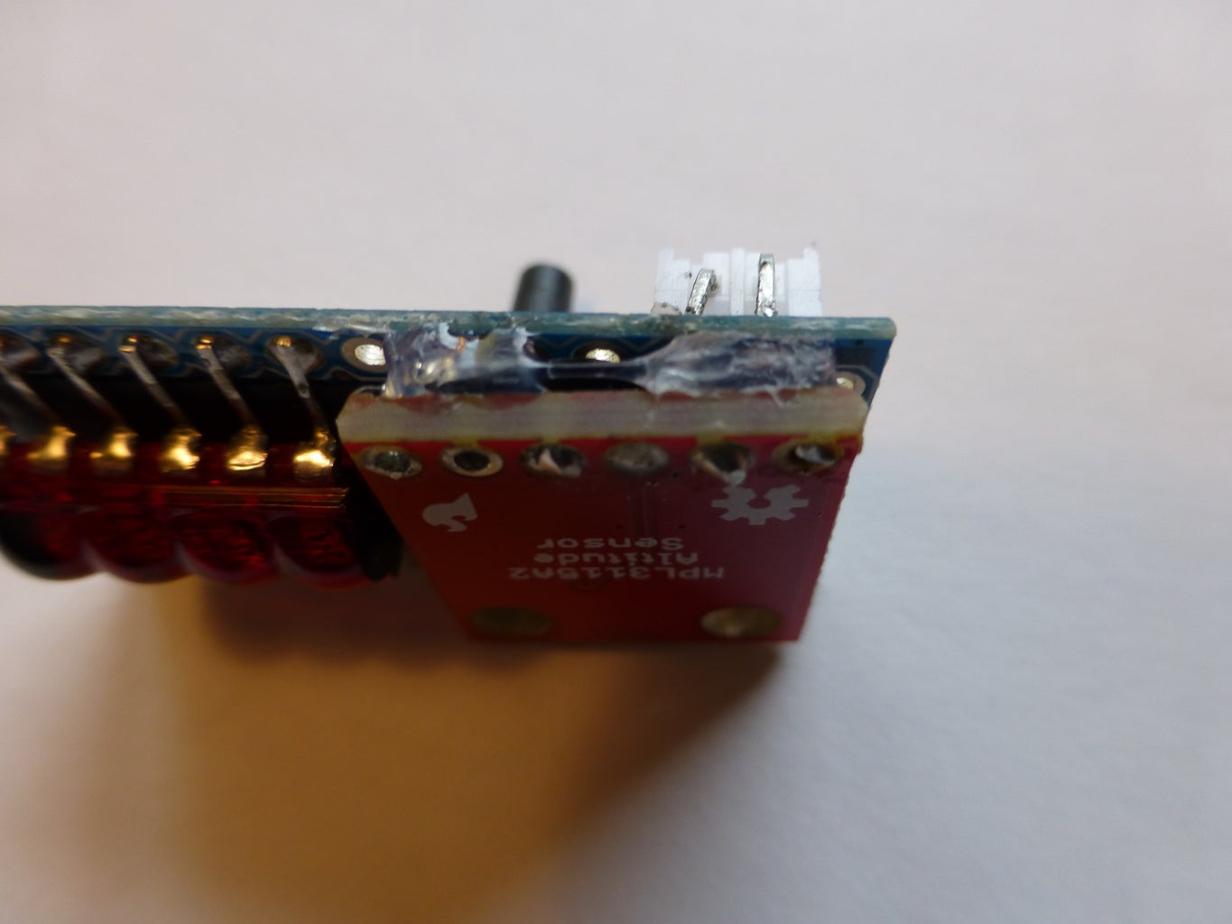
Connect the Altitude Sensor's SDA, SCL, VCC, and GND pins to the Arduino's A4, A5, VCC, and GND pins respectively with stranded wire. This can be tricky. I looped all the wires but the ground wire around underneath the sensor board to make it easier to work with as well as providing extra support to the board to keep it from rocking. I routed the ground wire directly from one GND pin to the other.
Make sure nothing is shorted. If there are any exposed wires that are close to each other, you can slip a piece of electrical tape between them and make sure it sticks.
After testing that your sensor is working and connected properly with some example code, glue it in place with hot glue. The sensor uses air pressure to detect altitude to make sure to leave space for air to reach the sensor. I just glued under each corner.
Step 6: Prepare and Install the Battery
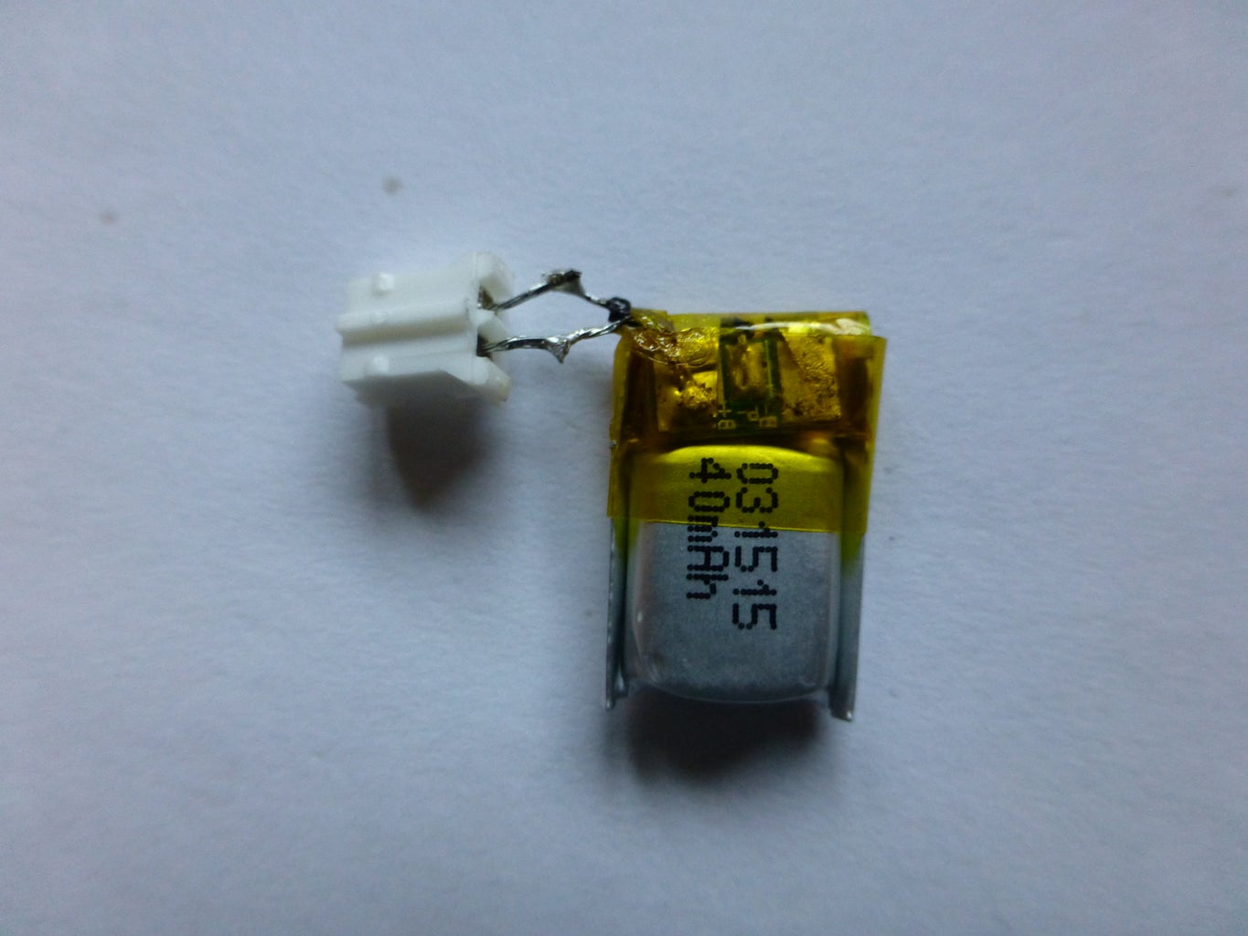

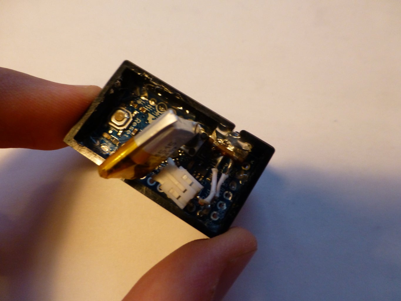
Next, the battery's wires need to be made much shorter so it will fit in the remaining space we have. Strip, cut and re-solder the wires so that they are very short.
Because of the short length of the wires that you are stripping, the rubber casing of the wire may come off completely. To fix the now-bare wires, I used liquid electrical tape, an insulative paint type material. This will keep the wires from shorting. You could also use heat-shrink tubing or regular electrical tape.
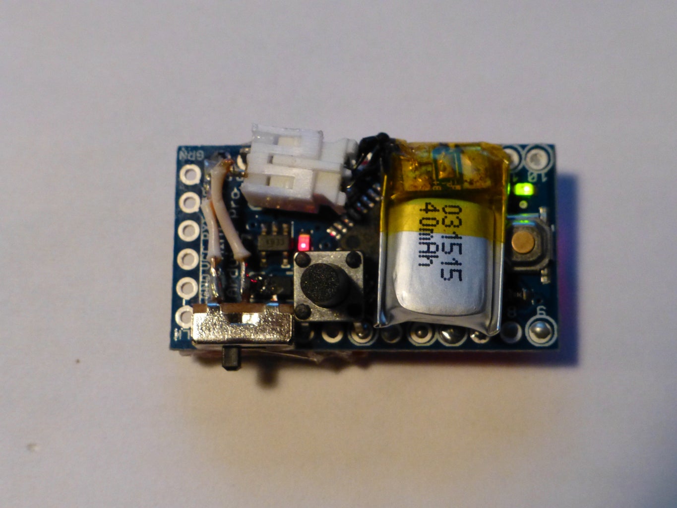
Now, all the electronics are in place. The last thing to do is the code.
Step 7: Upload the Code


Download the code for the Ultimate Altimeter here, and check the README to download the required Libraries. UPDATE 2021-03-15: I've included some of the libraries that folks were having trouble finding after all these years. Check the GitHub link above.
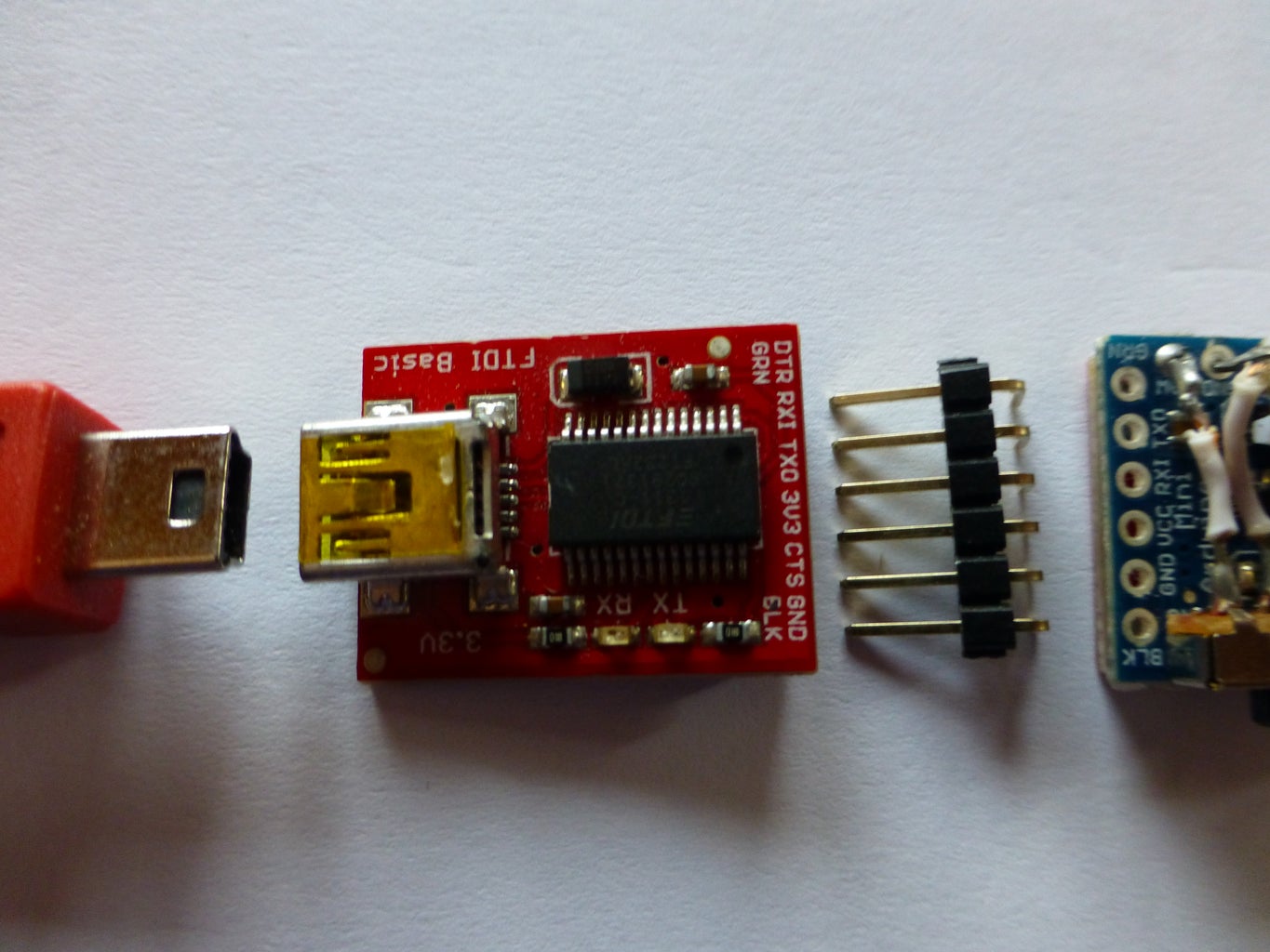
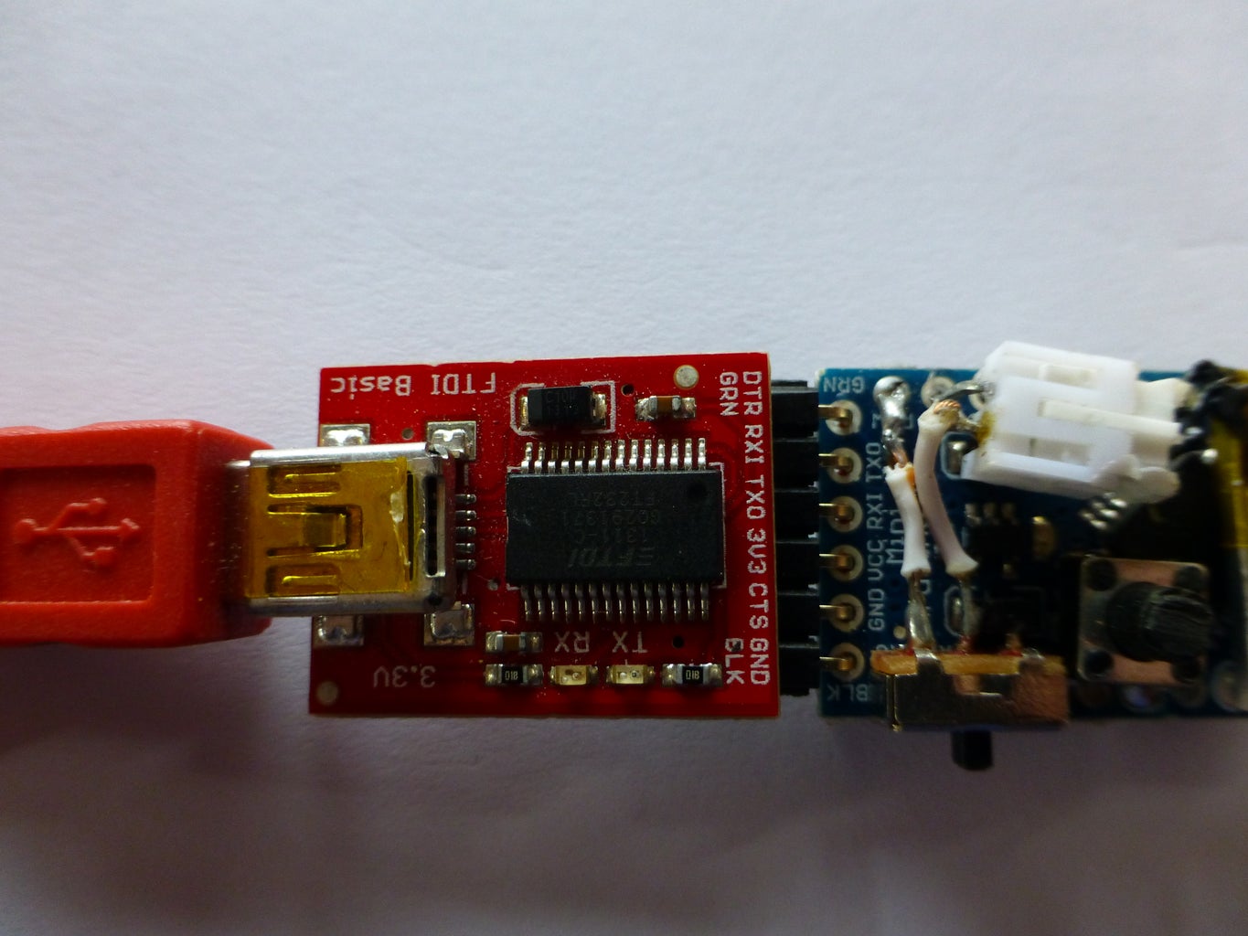
Once you have that ready, set up your uploading hardware. You will need a 3.3v FTDI Basic Breakout board, a right angle header, and a USB to USB Mini cable.
Hold the pin header into the Arduino's FTDI pins – no need to solder because you (hopefully) will only need to upload the code once – and use the Arduino IDE to upload the "Ultimate_Altimeter" sketch to the Arduino.
Your Ultimate Altimeter should be fully operational, but you might still want a case...
Step 8: Make a Case


You can 3D print case using the attached STL file, make your own case, or go without one.
You can also modify the attached file using TinkerCAD here, just make sure to share your improvements with me and others!
If you yearn for a 3D printed case either of mine or your own design, but don't have a 3D printer, head over to the 3Dprintmything subreddit on reddit and make a [WANT] post. Someone there will print one for you for a couple of bucks and ship it to you! Don't be scared because it's reddit. We are nice!
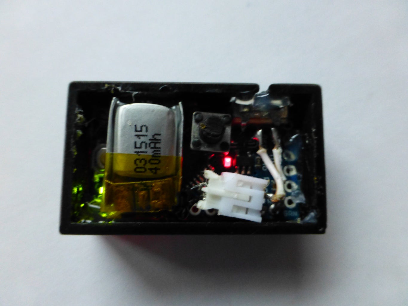
The printed case includes a slot above the hole for the switch. This is to aid in the inserting of the Altimeter into the case by making room for the movable plastic part of the switch. Push the switch to the middle in order to insert the Altimeter into the case. Once the Altimeter is in place in the case, hot glue it in there.

Step 9: Done!
Congratulations! You are done!
Here is a User's Manual I wrote up. It is included in the file downloadable from Github, and should answer most basic questions about the altimeter:
Ultimate Altimeter Users Manual1. Battery and Charging
A. The battery of the Ultimate Altimeter is a 40 mAh, Lithium Polymer (or LiPo) battery. It should last around 1 hour during normal use, last about 6 hours in Standby mode (see 2. B.), and should charge in around 30 minutes using the provided Mini-USB to JST charger. When not in use for long periods of time, store the battery at around half charge to keep it in good condition.
B. Due to the fragile nature of the battery's short wires (between the white JST connector and the rest of the battery), it is recommended that the JST connector never be fully inserted into the Mini-USB to JST charger. If it is fully inserted, it can be difficult to remove because of the tightness of the JST connectors on the battery and charger. In the event of this happening, use pliers or a similar tool to safely remove the JST connector. DO NOT pull on the battery's wires. The battery is charging if a red light is on on the charger. When the red light turns off, the battery is done charging.
C. If a battery breaks, is lost, or becomes unusable for any other reason, an extra can be purchased at this link: https://www.sparkfun.com/products/11316
2. Operating Instructions
A. The a Ultimate Altimeter has different modes with different functions.
I. "Alt" (Altitude mode) - Shows the current altitude.
II. "HiGH" (High mode) - Shows the highest altitude that the altimeter has been.
III. "Lo" (Low mode) - Shows the lowest the altimeter has been.
IV. "diFF" (Difference mode) - Shows the altitude you have covered ("High" - "Low").
V. "Stby" (Standby mode) - Turns the display off to save power. This mode could be used for a longer activity such as hiking where saving power is more important. It is not needed for RC Airplane flights because of their short duration.
B. Input Mechanisms
I. The button on the back of the Ultimate Altimeter is used to change modes. Press it once to cycle through to the next mode.
II. The switch on the Ultimate Altimeter turns it on and off.
C. Because the altitude sensor uses air pressure to measure altitude, strong winds or gusts may affect the readings on the Ultimate Altimeter. This can be seen by turning on the Ultimate Altimeter and blowing on it. The reading for current altitude should drop. This happens because the strong gust of air creates a negative pressure. This can be avoided in flight by placing the Ultimate Altimeter in a cargo compartment or other wind-protected area to keep it out of strong gusts of wind. This is not a necessity though; in test flights with no wind protection, measurements only wavered a couple of feet, and the "Difference Mode" was not affected.
The Ultimate Altimeter was designed and created by qubist (/u/qubist1 on reddit).
Share your creation with the world! It would make me smile to see others' Ultimate Altimeters.
Have fun!

Finalist in the
Launch It! Contest

Participated in the
Sensors Contest

Participated in the
Battery Powered Contest


