

Introduction: Soda Can Theremin


Remember those old-school sci-fi movies with squeaky and eerie background music? Those unique sounds were made using a theremin, an electronic instrument that can be played without physical contact. When playing a theremin, the operator can control volume and pitch with his or her hand position relative to two antennas.
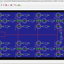
This project is going to demonstrate how to build a simple theremin on a breadboard using a soda can as the antenna! With simplicity in mind, the theremin in this project will only demonstrate pitch modulation. The design that is implemented is shown in the block diagram above. However, it doesn't take too much extra work to add volume control, so I encourage you to try it if you're looking for an extra challenge.
To keep it short and sweet, we won't get too deep into the theory of how a theremin works. Briefly though, the antenna (our soda can) acts as one plate of a capacitor. Your hand will act as the other plate of the capacitor. Thus, by moving your hand nearer and further from the can, you are changing the capacitance. This takes place within the variable-frequencyoscillator portion of our circuit. As the capacitance in the oscillator changes, the oscillator's output frequency changes as well. This change in frequency can be heard at the speaker at the end of our circuit.
Step 1: Gathering the Materials

This project is completed using the Digilent Analog Discovery and Analog Parts Kit. The only other part needed is the soda can! Any metal object with a reasonable surface area would work as well.
The specific parts used in this design are shown in the picture above.
- OP27 Operational Amplifier (x2)
- OP37 Operational Amplifier
- Small speaker
- 100pF Ceramic Capacitor
- 0.047uF Ceramic Capacitor
- Small-signal Diode (1N3064)
- 10kΩ resistor (x2)
- 20kΩ resistor (x2)
- 47kΩ resistor (x2)
- 100kΩ resistor (x3)
- a few breadboard pins and jumper wires
- Breadboard (not pictured)
- Soda can (not pictured)
- Digilent WaveForms Software (Free Download)
All of these parts are right out of the Analog Parts Kit.
Step 2: Variable-Frequency Oscillator

Before getting started with the design process, a clarification on these instructions should be mentioned. The circuit will be built all on the same breadboard, one part at a time. I recommend starting towards the left of your breadboard and working towards the right to make sure it all fits. Towards the end, in step 6, an image of the circuit in its entirety is included so you can check and make sure each portion of the circuit is connected properly. It wouldn't be a bad idea to take a look at the image in step 6 first to get an idea of what the final product looks like.
Moving on with the design process now. For the variable-frequency oscillator, we will be using the OP27 operational amplifier. The pin out and specifications of the OP27 can be seen in the data sheet.
- Place the op-amp such that it straddles the valley of the breadboard and the notch is to the left.
- Since we will be connecting power and ground at several locations, it is easier to use jumper wires. As a personal preference I like to keep my jumper wires color-coded.
- Connect one end of a red jumper wire to the spot marked "+5V". This is pin 7 of the op-amp.
- Connect one end of a white jumper wire to the spot marked "-5V". This is pin 4 of the op-amp.
- Connect one end of an orange jumper wire to the spot marked "Vout". This is pin 6 of the op-amp.
- Connect one end of a black jumper wire at the spot marked "GND".
- Now we'll place the resistors. All the resistors used in the oscillator are 100kΩ.
- Place one resistor across the op-amp from pin 2 to pin 6.
- Place another resistor across the op-amp from pin 3 to pin 6.
- Place the last resistor between the grounded row of the breadboard and pin 3 of the op-amp.
- Place the 100pF capacitor between the grounded row of the breadboard and pin 2 of the op-amp.
- The soda can is to be placed in parallel with this capacitor.
- Connect one end of a green jumper wire to pin 2 of the op-amp. You will hold the other end of this wire in your right hand when operating the theremin.
- Connect one end of another black jumper wire to the grounded row of the breadboard. Connect the other end of this wire to the soda can. A slightly longer jumper wire is easier here. I place the wire such that it is held on by the tab on the top of the can. Taping the wire to the can would work as well. Just make sure there is metal-to-metal contact.
- By holding the green wire in your right hand, your body is now part of the circuit. This allows you to use your left hand to act as a plate of a capacitor with the soda can.
Step 3: Weighted Summer

To save space on our breadboard, we will use the Analog Discovery's Arbitrary Waveform Generator (in the WaveForms Software) to act as the fixed oscillator. On the Analog Discovery device, this is the yellow wire labeled "W1".
This next portion of the circuit, the weighted summer, mixes the signals from our fixed and variable-frequency oscillators. We will be using another OP27.
- Move 5 or 6 holes down from the oscillator and place the OP27 such that it straddles the valley of the board and the notched side is on the left.
- Just as we did when building the oscillator, connect one end of red, white, and orange jumper wires at "+5V", "-5V", and "Vout", respectively.
- Connect one end of a black jumper wire where "GND" is shown at pin 3 of the op-amp.
- Connect two 47kΩ resistors in in parallel as shown in the breadboard image. The right side of both resistors should be connected to pin 2 of the op-amp. The left sides of the resistors should be off by one row as shown.
- In the breadboard image above, "Vin" is the output voltage from our oscillator that was built in the previous step. That being said, connect the other end of the orange wire from the oscillator to the spot marked "Vin".
- Place a breadboard pin at the spot marked "WaveGen Input". This will be connected to the Analog Discovery to act as our fixed oscillator.
- Lastly, place a 20kΩ resistor across the op-amp from pin 2 to pin 6.
Step 4: Envelope Detector

By mixing the oscillating signals with the weighted summer, a "beating" signal is produced. The new signal output from the weighted summer will be passed through an envelope detector which traces the beating pattern.
- A few holes down from the weighted summer, place the small signal-diode. Note: The orientation of the diode is very important. The diode in the Analog Parts kit is orange with a black band on one side. Place the diode such that the black band is towards the right and the orange side is to the left.
- "Vin" for the envelope detector is the output of the weighted summer. Connect the other end of the orange wire at pin 6 of the weighted summer's op-amp to the left side of the diode.
- At the right side of the diode, place the 10kΩ resistor and 0.047uF capacitor in parallel.
- Connect one side of a black jumper wire at the right side of the resistor and capacitor. This will connect to ground. This location is at the spot marked "GND" in the image above.
- The output from this circuit is at the junction of the diode, resistor, and capacitor. Connect one side of an orange jumper wire at the spot marked "Vout".
Step 5: Amplifier

The output signal of the envelope detector is actually ready to send to a speaker, it just wouldn't be very loud. That being said, the final step before sending the signal to the speaker is an amplifier. The amplifier used here is an inverting amplifier built with an OP37 op-amp. The OP37 has an identical pin out compared to the OP27. It behaves similarly as well. If you're interested though, here is the data sheet specific to the OP37.
- Moving a little further down this time (about 12-15 holes), place the OP37 the same way the OP27's were placed, straddling the valley of the board with the notch to the left.
- As with the previous two op-amps, connect one end of the red, white, and orange jumper wires at "+5V", "-5V", and "Vout", respectively.
- Place a 20kΩ resistor across the op-amp from pin 2 to pin 6.
- Place a 10kΩ resistor such that the right side of it is connected at pin 2 of the op-amp. The left side of the resistor should be connected a few holes to the left of the op-amp.
- Connect the other side of the orange wire from the envelope detector's output at the spot marked "Vin".
- Pin 3 of the op-amp would normally be connected to ground through a resistor. It is ideal to use as large of a resistor as possible, hence the infinite resistance depicted in the schematic. To simulate an infinite resistance, we will leave pin 3 unconnected such that it sees an "open circuit". No current can flow through an open circuit it so it acts as an infinite resistance.
Step 6: Circuit Review and Completion

Above is a breadboard image of the circuit as a whole. The last step to complete the circuit is to connect the power supplies and speaker.
- Start by placing 4 breadboard pins in a line between the envelope detector and amplifier as shown.
- The pin furthest to the left will be connected to the Analog Discovery's "+5V".
- The second pin in from the left will be connected to the Analog Discovery's "-5V".
- The last two pins will both be connected to one of the Analog Discovery's grounds.
- By doing this, we have one full row of +5V, one full row of "-5V, and two full ground rows.
- Connect the free ends of all of the red jumper wires to the +5V row.
- Connect the free ends of all of the white jumper wires to the -5V row.
- Connect the free ends of all of the black jumper wires to one of the two ground rows.
- Place the speaker a few holes down from the amplifer. The speaker's orientation does not matter.
- Connect the other end of the orange output wire of the amplifier to one side of the speaker. Use a black jumper wire to connect the other side of the speaker to ground.
- Connect the Analog Discovery to the circuit as labeled in the breadboard image and check all of your connections. Note: "AWG" in the image stands for Arbitrary WaveForm Generator. This is the connection mentioned in step 3 that will act as the fixed oscillator. It is the yellow wire on the Analog Discovery device marked "W1".
Step 7: Operation
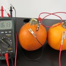
Watch the video above to see the soda can theremin in action!
- If you have not yet downloaded the Digilent WaveForms software, download it here. It's free on the Digilent website!
- I'm assuming that if you have the equipment to complete this project you have some experience using the Digilent WaveForms software. If not though, check out some of these pages. They quickly explain how to do the basics that we will need for this project.
- Connect your Analog Discovery and open the WaveForms software. Open the Voltage Instrument and turn on V+ and V-.
- To get the most variation of frequency in our final output signal, we want the initial frequency of the variable-frequency oscillator to be as close as possible to the fixed oscillator. That being said, the first thing we want to do is measure the output frequency of the variable frequency oscillator. You can do this with the Analog Discovery's Oscilloscope or any other oscilloscope of your choice. When doing this measurement, hold the green wire in one hand, but keep your other hand awayfrom the can for now. The value that you measure here will be the value that you set the WaveForm Generator frequency to. Don't forget to turn on the DC power supplies so the op-amps have power!
- Open WaveGen in the WaveForms software. Select a sinusoidal wave for channel 1. Set the frequency to be the frequency you measured in step 4. For example, I measured the output frequency of my variable-frequency oscillator to be 25.67kHz so I set the frequency in the waveform generator to 25.7kHz. (Your measured frequency should be between 20kHz and 27kHz.) Set the amplitude of the wave to 5V and offset to 0V.
- Make sure your DC power supplies are still on. Now click "Run AWG 1" or "Run All" in the waveform generator. Your theremin is now ready to play! Hold the green wire in your right hand and play the theremin by moving your left hand nearer and further to the soda can.
Note: This circuit is extremely sensitive to "noise" from other electronic components. A nearby phone or laptop charger could cause a big difference in the result. Make sure all nearby chargers are unplugged. Power supplies for desktop computers usually do not create any issues. If your circuit is not functioning properly check for other possible sources of interference.
Feel free to contact me with any questions. Good luck and have fun!


