

Introduction: Thomas Jefferson Wheel Cypher


In this Instructable, I will build a Wheel Cypher that was invented by Thomas Jefferson in the early 1790’s. His was made from wood. For this one, I will be using modern technology – a 3D Printer. Hopefully by reading this Instructable, you will learn a little history, learn how to use Google Sketchup, learn a little bit about printing with ABS, learn a little Microsoft Excel, and end up with a Cypher that you can use with a friend.
This project was inspired by another member’s comment on my last Instructable where I built a Cryptex. You can check out that Instructable here: https://www.instructables.com/id/From-IDEA-to-PRODU...
Cipher versus Cypher: Although it is more common to use the Cipher spelling, Thomas Jefferson had called it a “Wheel Cypher” and so that is what I will use here.
Step 1: Thomas Jefferson's Design

In Thomas Jefferson's writing, he starts with a 2” diameter piece of wood that is about 6-8 inches long. He bores a hole through the center to allow it to be mounted on an axle and then slices the wood into 1/6” thick discs. Based on the example in his writing, I believe he created 26 discs.
On each disc, he segments it into 26 sections and writes the letters of the alphabet randomly, such that each letter only appears once on a wheel. No two wheels should be the same. He then numbers each wheel so that they can be placed on the axle in a desired order.
After completing the first Cypher, the process is repeated to create an identical Cypher. One is used by the sender to create the coded message and one is used by the receiving person to decipher the message.
To use the Wheel Cypher, the sender creates the message. First, turn the wheels until the desired message (without spaces) is read on one of the lines. This leaves 25 different lines that the sender can choose as the code. He picks any of these lines and writes them down. He continues to do this for any additional messages. These are then sent to the reader who then enters the codes on her set. (They must agree on the order of the discs ahead of time or include the order as part of the message.) She then rotates the whole Wheel Cypher until one of the lines forms an understandable message. Jefferson went into further discussions about how to represent numbers, if desired, and also did some calculations.
This seems to be a very simple concept, but would be very difficult to decipher without modern computers.
There are images available of his actual notes on the Wheel Cypher here:
http://memory.loc.gov/cgi-bin/ampage?collId=mtj1&f...
Someone (thankfully) has taken the time to type this up for us so we don’t have to try to read his handwriting on paper that has deteriorated for 200 years. The typed version can be found here:
http://ciphermachines.com/jefferson2
Here's another site that had helpful information:
Step 2: Design the Wheel


For designing this Wheel Cypher, I will be using Google’s Sketchup 8 on a Windows 7 computer.
My 3D printer requires .STL files or .OBJ files. Sketchup 8 does not support these file types. But, there is a Plugin available that can create .STL files.
Here are links to the software packages that I am using here:
Sketchup: http://www.sketchup.com/
Sketchup PlugIn to Export STL files: http://extensions.sketchup.com/en/content/sketchu...
First, Open Sketchup and select the template for designing. Our printer reads everything in millimeter (mm) measurements. If we design an object as 2”, the printer reads this as 2mm. So, we need to develop everything in mm. In Sketchup, we choose the “Product Design and Woodworking – Millimeters” template.
Per Thomas Jefferson’s description, we want the finished cylinder to be 2 inches in diameter and 6 to 8 inches in length. So, our first step is draw a circle of 2 inches in diameter. To assist us with aligning the letters, we’ll draw it with 26 sides to create the full alphabet on one ring.
To get a 2” diameter, we use the circle tool. Click on the origin, move the mouse out some distance and then click again. This will draw a circle. To set the radius of the circle, you can now just type in the desired radius. In this case, we’ll type “25.4” and hit ENTER. (1 inch radius * 25.4mm/inch) To create the 26 sides, we type in “26s” and hit ENTER.
Instead of boring an axle hole through, we get to design the axle hole into ours. For this design, I have decided to use a ¼” threaded rod for the axle and use knobs on the ends to tighten down. This design will allow us to tighten down the wheels to keep them from moving while we are looking for the message. To create our hole, we draw a circle of radius 3.5mm. A 1/4 inch rod would actually have a radius of 3.18mm, but we want the wheels to slide on easily so I chose a radius of 3.5mm. We don’t need this circle to be 26 sided, so I type in “100s” to make it more like a true circle.
To keep the wheels from rubbing fully against each other, I have decided to add a “hub” extension on one side of the wheel to separate it by 1mm from the next wheel. To create this, I add a circle with a radius of 6mm. We don’t need to type “100s” this time, Sketchup will use the last setting used.
Now we want to make our wheel thickness. Using the Push/Pull tool, select the biggest wheel surface and pull it up some distance. Type “6” and press . This will create a thickness of 6mm, or roughly 1/6 inch, as suggested by Thomas Jefferson. Next, grab the hub ring with the Push/Pull tool and pull it up 7mm. This will create the hub extension 1mm beyond the disc surface. At this point, Sketchup still has a surface in the center of the wheel. To remove this, simply click on the surface and press DELETE .
We now have a basic wheel. In fact, if you made the outer ring 100 sided instead of 26 sided, you could use this for building a toy car.
At this point, we could export this as STL and print it. But, it isn’t really visually appealing. So, let’s add some decoration.
Step 3: Make It Pretty


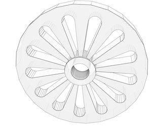
I have decided that I will make spokes to decorate this.
To do this, I invert the image by using the orbit tool so that I can work on the same plane that has the origin point. Since there is an even number of segments, I can draw lines between the points on the outer ring to an opposite point and that line will go through the origin point. I draw all of these lines, creating pie slices.
For this wheel, I have decided that I want a 3mm "Rim". So, from the origin point, I draw a circle with a radius of 22.4mm. (25.4mm - 3mm) I could delete out every other spoke at this point, but I think it would look nicer if it had rounded edges at the rim. To do this, I create another circle from the origin with a radius of 19.4mm. (3mm from the last circle.) To create the rounded spoke, I use the arc tool; click on an intersection of a spoke line with the 19.4mm radius circle, then click on the next spoke line that intersects with the 19.4mm circle. Using the mouse, I then pull the arc until it reaches the 22.4mm radius circle. See the picture of how it looks at this point.
Next, using the pointer, select each of the line segments that make up the 19.4mm radius circle and the 22.4mm radius circle and delete them. These were just guides and are no longer needed. We also delete the lines from the arcs to the outer edge, the lines from the outer edge of the hub to the origin point, and the surface that got re-created over the axle whole. Again, see the pictures to see how this looks without the guide lines.
Using the Push/Pull tool, push in each spoke hole 6mm to create the spokes.
That's it!
Save the file as .SKP, which is the native file type for Sketchup. We’ll want this format if we decide to modify this design later. To be able to print, though, we’ll need to export this as .STL. Export the file by selecting “Export STL…” from the File Menu. In the popup menu, select the units to be Millimeters and leave the file format as Binary.
This part is now ready to take to the printer.
Step 4: Print It.

Materials:
- 3D Printer (We’re using a Prusa-i3)
- Computer with 3D Printing software, such as Repetier and Slic3r
- PPE (Eyeware, gloves, masks)
- Printer Filament (we used 1.75mm ABS)
- Acetone
- Camel Hair Artist Paint Brush
- Razor Scraper
- Sand Paper (220 grit)
WARNING: Acetone and its fumes can irritate the nose and throat and can cause moderate to severe eye irritation. Use PPE and work in a well ventilated area. I recommend printing in a well ventilated area as well.
PREPARE THE PRINT FILE:
I use Repetier for controlling my printer. I downloaded it from here: http://www.repetier.com/
First, I load the desired part into my Repetier software and place it in the orientation that I would like to print. I can actually print 4 at a time on my print bed. Don’t forget, you’ll need to create 2 sets of everything, so you’ll be doing a lot of printing. Another option is to create a mold and cast each of the parts, like I did on my Cryptex design.
NOTE: Upon loading the .STL file into Repetier, it may give a warning stating that it is not watertight. This means that not all edges and surfaces are secure (water would leak through). It recommends that we use a Model Repair Service. I use the service that they recommend. It’s a free Online service that you upload your model to, it repairs the model, and then you download it. Here’s the link to that service.
LINK: https://netfabb.azurewebsites.net/
Next, we need to create the GCODE that will be used for running the printer. GCODE is a list of commands that tell the printer when to turn on heat, what temperature, what positions to move to, … For creating the GCODE, we used Slic3r. It is a stand-alone software that comes packaged with Repetier software. Slic3r breaks down the model into layers that will be printed.
Before Slicing, we need to set up our print parameters. I won’t go through all of the parameters, but here are the more important ones that I use when printing with ABS.
- Extruder Temp: 230 degC
- Bed Temp: 110 degC
- Perimeters: 3
- Bottom Layers: 3
- Top Layers: 3
- Fill Percentage: 60%
Now that we have the program ready, we prepare the printer and print the parts. Please refer to my other Instructable where I go through the steps of leveling the bed, preparing the heat bed to get the printed ABS to stick, and also notes on delamination. I did not have any delamination while printing these parts, but this information may still be useful to you. I typically only run into this issue with taller parts.
PRINT IT.
REMOVE THE PART:
After printing is complete I use a scraper razor blade and remove the part from the bed. Any of the slurry film that comes off with the part can be eroded away by brushing acetone on the part.
PREPARE THE WHEELS:
At this point, the printed part has little ridges on the edges where each layer was printed in creating the part. Trying to hand write our letters on this would be frustrating, so we need to sand down the edges to smooth them out. I first brushed on acetone and let it dry. Acetone eats away plastic and smooths it out a little. I then use a block sander and sand each segment of the wheel. I continue this process of acetone and sanding until I am satisfied with the wheel.
After you are satisfied with the smoothness of the wheels, you are now ready to write the randomized letters on the wheels.
Step 5: Create the Coded Wheels


I now need to write the letters of the alphabet on each wheel in random order. One method for doing this is to write all of the letters out on a piece of paper. For each letter I randomly choose, I cross it off of the list. I start each wheel with the hub sticking out to the right. I then write the letter A on a segment that has a spoke. On the spoke, I write a unique number. My set is actually only 13 wheels wide; my wheels are numbered 1-13. If I were to actually create a 26 wheeled cypher, I would probably use letters of the alphabet to identify each wheel (A-Z).
Create one set of wheels, with each wheel having a unique random order of letters. Then, create an exact duplicate of the wheels for the second set.
If you don’t trust yourself to create random sequences? Try this:
Open Microsoft Excel. Fill Cells A2 thru A27 with the alphabet. (Cell A2=‘A’, A3=’B’, A4=’C’, …) Type the letter A in cell B2. In cell B3, type in =INDEX($A$2:$A$27, LARGE(MATCH(ROW($A$2:$A$27), ROW($A$2:$A$27))*NOT(COUNTIF($B$1:B2, $A$2:$A$27)), RANDBETWEEN(1, ROWS($A$2:$A$27)-ROW(A2)+1))). But, instead of pressing ENTER after typing in the formula, press SHIFT+CTRL+ENTER. This will temporarily put { and } brackets around the formula. Now copy cell B2 and paste on cells B3-B27. This will create a unique list of letters where every letter is only used once. These will change any time there is a change in the spreadsheet, such as typing the number 1 into cell C2.
I copy the randomized letters and use "Paste Special - Values" to paste them into different columns to have a record of each wheel.
For more information on this formula, go to this link:
http://www.get-digital-help.com/2009/07/03/how-to-...
HOW MANY DIFFERENT WHEELS ARE THERE?
Let's do a little exercise to find out.
Let's say we only have 2 letters. Since these are on a wheel, we can always rotate the wheel so that the letter "A" is our starting point. As such, there is only 1 possible combination; AB.
3 Letters: abc / acb - 2 combinations
4 Letters: abcd / abdc / acbd / acdb / adbc / adcb - 6 combinations.
5 Letters: abcde / abced / abdce / abdec / abecd / abedc / acbde / acbed / acdbe / acdeb / acebd / acedb / adbce / adbec / adcbe / adceb / adebc / adecb / aebcd / aebdc / aecbd / aecdb / aedbc / aedcb - 24 combinations
Based on these combinations, it looks like the number of combinations could be represented by:
n=2 letters: (n-1) = (2-1) = 1 combination
n=3 letters: (n-1)*(n-2) = (3-1)*(3-2) = 2*1 = 2 combinations
n=4 letters: (n-1)*(n-2)*(n-3) = 3*2*1 = 6 combinations
n=5 letters: (n-1)*(n-2)*(n-3)*(n-4) = 4*3*2*1 = 24 combinations
This type of calculation is called a factorial and is represented by an exclamation point. ie 4! = 4*3*2*1
So, since we have 26 letters in the alphabet. Taking off the letter A, since it is fixed. We have 25! combinations. Or:
1.551121e+25
Step 6: Alternate Wheel - With Printed Letters


This is an Alternate Wheel that I designed for printing with letters. The wheel is the same design as before, but I placed holes under each letter section. The intent of this was to be able to slide a rod through the whole assemble to help keep everything lined up.
After adding the holes, I created the lettered sections. First, I orbited around to look at the bottom of the wheel. I then used the rotation tool to rotate the wheel so that one of the section intersections was aligned to an axis. Doing so aligned a flat section to the other axis. To rotate, I clicked on the origin, clicked on a intersection between two letter sections, and then rotated and aligned this point to an axis.
Since I want the letters vertical on the wheel, I need to rotate the wheel vertical. I use the rotation tool, click on a point that meets an axis, click on a point vertically from this, and rotate the wheel to align to another axis.
Create the Letter Tiles:
With the lettered surface facing me, I draw lines horizontally on the top and bottom of one of the tiles. Using the pointer, I select the 4 lines and surface that create a letter tile and copy that box. I then paste this box off to the side. Paste enough times to create 26 tiles.
To determine the size of the letters, I measure the height and width of the tile. Then, using the 3D Text tool, I print a letter W (the widest) and a Letter Q (the tallest) to make sure that they will fit within the tile. Adjust the letter sizes until the letters fit.
I adjust the letters to be centered on each tile. Then, I right click on the letter and select "Explode". This breaks the letter group into each of its line segments. Using the Push/Pull tool, I pull each letter to 0.5mm from the surface. (My first attempt was 1mm, but because the letters were so small, they grew in thickness as they were printed.) When using the Push/Pull tool, if the centers of the letters (A, B, D, O, P, Q, R) get pulled with the rest of the letter, you can draw a line tracing one of the other lines making the center and it usually separates the center surface from the letter surface.
Next, using the pointer tool, I draw a box around each individual tile. Then, I right click and select "Make Group". This allows me to select the letter with one click.
Save this file for later to allow for dragging the letters in random order to create different wheels.
I can now drag the letter on to one of the segments of the wheel. I select the upper left corner of the tile from its back side, I then move that tile to the upper left of one of the wheel segments. If the tile sits off from the wheel on the bottom, I then orbit to the side of the wheel and rotate the tile piece until it snaps to the wheel.
I had some problems printing the wheel at first. I found that if I selected every letter and exploded it, and then selected everything and chose "Interact Faces", I had better success.
Before creating the STL files, I rotate the wheel to lay flat with the Hub sticking up. Export as STL and you are ready to print.
Step 7: Assemble the Wheel Cypher


Materials:
- 1/4" - 20 Threaded Rod, 3 ft length
- (4) washers (not shown)
- (4) Knobs with 1/4" - 20 threads
- Tape
- Hacksaw
- File
Cut the Axle:
- Slide all of the wheels for one set onto the threaded rod and screw one knob on fully. If you want to add separation after every 4th or 5th character to aid you in writing down codes, you can add washers to the assembly. You should add those now before cutting the axle to length.
- With the wheels pushed tightly against the knob, wrap tape around the rod; this will determine where we cut the axle.
- Remove the knob and the wheels.
- Draw a line on the tape about 1/4" end from the edge where the wheels were.
- Cut through the rod on the line.
- Remove the tape.
- File the rod to remove any sharp edges and to clean up the threads.
Tip: If you thread on a nut before cutting the threaded rod; you can remove the nut and it will straighten out the threads.
Assemble the Wheel Cypher: Knob, washer, wheels, washer, and knob.
Step 8: Send a Message to a Friend

To use the Wheel Cypher, give one wheel to a friend and keep the other one. You must decide beforehand how to orient the wheels so that messages can be sent and decoded.
Simple method: Number the wheels 1 thru 26 (or A thru Z) and always use them in order from 1 to 26 (or A thru Z). National Publication method: Number the wheels A thru Z. When creating a message, include the date. The date can then be used to find a national publication from that day. Then, the wheels get oriented as they occur in the 1st sentence of the 1st paragraph on the 1st page (or whatever sentence, paragraph, or page you choose.) Then, Code the message and send it. The Receiver will then need to find that same publication for the date that you specified. In this manner, the order of wheels becomes randomized.
You can make up any method that you want, it just has to be useable by the recipient, too.
Create the Code:
Align the wheels to create your message. In the picture above, the message is "Instructables" (outlined in green). Tighten the knobs to hold this message tight. Rotate the whole assembly and choose any of the other 25 lines and write down the coded message. If we go down 3 lines, we can use "COJC ZSSF RTBXB" (outlined in blue). Repeat this step for all messages, using any of the coded lines each time.
TIP: For creating separation to assist you in aligning the letters, you can add washers between the wheels.
Retrieve the Code:
Align the wheels as agreed upon. Enter the code that you have received "COJC ZSSF RTBXB" and tighten the knobs to hold tight. Rotate the whole assembly and look for a line that has a readable message. Read the message. "INSTRUCTABLES".
Step 9: Thanks for Reading
Thanks for taking the time to read this Instructable. Hopefully, you have found it interesting and it inspires you to create something of your own.
I have attached the Sketchup File and STL file for the Simple Wheel that I have used in creating this Instructable.
I have also attached the Sketchup File for the Alternate Wheel with the lettered tiles.


Participated in the
Protected Contest


