

Introduction: Time Scheduled Switch With ESP8266 and Blynk


Most of the times when we go out of home for some days, we think of having some device that could switch ON/OFF (let's say) Refrigerator (or any other important appliance) for some hours during the day.
Today, we are going to make such time scheduled electric switch which switches ON/OFF at times which we set the in our Blynk app. Woah!
Let's begin!
Step 1: Things We Need

- Hardware:
- 5V relay
- NodeMCU
- Jumper wires
- Breadboard
- 3V3 and 5V power source
- Electrical Wires
- Software:
- Arduino IDE
- BLYNK app
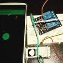
Step 2: Circuit and Connections

It's circuit is same as we have created for our Smart Switch. So, if you already have that circuit set up, go ahead with Blynk app set up and Start playing.
Connections:
- D5 pin of NodeMCU connects to IN1 pin of 5V relay.
- 3V3 of NodeMCU connects to 3V3 powers source and GND to GND.
- Vcc of relay connects to 5V source and GND to GND.
- Live wire is connected directly to appliance.
- Neutral wire from source comes to relay NC pin and another wire goes out from COM pin which is connected to the appliance.
Step 3: Let's Set Up the Blynk App


- Create a New Project in BLYNK app.
- Write Project Name and Select NodeMCU from dropdown and WiFi as connection type.
- An AUTH token will be sent to your registered email, note this down.
- Tap on the screen and add the Eventor widget to the screen.
- Tap on the Eventor widget and click Add New Event.Select Time button and choose DAYS OF THE WEEK and START AT time and TIME ZONE.
- SET THE TIME, then tap OK.
- Now, select turn ON pin and add D5 pin as we have connected our relay to PIN D5.
- Tap OK to finalize your Start Event.Same way create a new event and select START time that will Switch OFF the relay at PIN D5.
We have completed the circuit and set up our BLYNK. Let's do some coding.
Step 4: Code
#define BLYNK_PRINT Serial
#include <Esp8266WiFi.h>
#include <BlynkSimpleEsp8266.h>
// You should get Auth Token in the Blynk App.
// Go to the Project Settings (nut icon).
char auth[] = "YOUR_AUTH_ID";
// Your WiFi credentials.
// Set password to "" for open networks.
char ssid[] = "WIFI_SSID";
char pass[] = "WIFI_PASSWORD";
void setup()
{
  // Debug console
  Serial.begin(115200);
  Blynk.begin(auth, ssid, pass);
  // You can also specify server:
  //Blynk.begin(auth, ssid, pass, "blynk-cloud.com", 8442);
  //Blynk.begin(auth, ssid, pass, IPAddress(192,168,1,100), 8442);
}
void loop()
{
  Blynk.run();
  // You can inject your own code or combine it with other sketches.
  // Check other examples on how to communicate with Blynk. Remember
  // to avoid delay() function!
}
Make sure to change the AUTH_KEY, SSID and PASSWORD before uploading the code to NodeMCU.
Step 5: Upload and Play

Connect NodeMCU using the MicroUSB cable and upload the code using Arduino IDE.
Once uploaded, click Play button on the BLYNK app and we can now close the app. The app will do rest.
We can now schedule our appliances to turn ON/OFF whenever we want. That's what we call some good use of technology.
Follow knowshipp.com for more projects.

Participated in the
Microcontroller Contest 2017


