

Introduction: Transforming Tree 3D Printed Toy


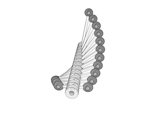
Twist one way and this toy turns shows a slow spiral pattern. Spin it the other way and you get a very different stairstepping pattern. It's all a matter of playing with angles of rotation. Thanks to parametric design and 3D printing it's a quick path from idea to reality.
This project was inspired by John Edmark's Helicone.
Step 1: OpenSCAD

OpenSCAD is a horribly ugly little program that can do wonderful things if you like thinking in arrays and loops. The process of learning it takes a couple hours, but it's free and worth the time. Here's a quick overview of how I got into it.
- Download OpenSCAD. It's free for OS X, Windows, and Linux
- Connect it to a real editor like Sublime Text 2. Here's how.
- Go through some tutorials.
I'm a math geek so all of this appeals to me, but I understand if you're normal and don't want to do it. The print files are coming up soon, I promise.
OK, parametric folks, let's do this.
Step 2: The Connector

The basis of this whole toy is the way that each piece connects with the other. There is a rectangular shape that extrudes down from each piece. There is a corresponding indentation on the top of each piece. This indentation determines the pattern for the whole toy. Here it allows for an 8 degree rotation clockwise and a 40 degree rotation counterclockwise.
This one connection is pretty much all that's going on here. With that working it's just a matter of tweaking the angles until it looks good. This allows for a 48 degree range of movement.
If you wanted to, you could alter it to a one-sided extrusion for a larger range like 300 degrees, but that takes a lot longer to spin the whole toy to change states. With 11 pieces in the toy that's 528 total degrees to change states. Change to 300 degrees and that's 3,300 degrees, just over 9 full rotations.
OK, now let's create this in OpenSCAD.
Note: I'm not an expert OpenSCAD user and I'm seeing ways that my code could be cleaned up, but it works right now so... there it is.
Step 3: Start With a Cylinder

Hells yeah, primitives!
Here's the code:
cylinder(h=ballHeight+margin, r=connectorWidth/2, $fn=50)
I'm using variables in this where ballHeight is the vertical radius of the flattened spheres on the end and margin is the margin added as a space between balls so there would be oom if they were right on top of each other. So doubling this and adding 1 gives a 1mm gap between the spheres if they were directly on top of each other. The connectorWidth is the diameter of the cylinder and since cylinders are determined by radius this is cut in half.
The "$fn=50" refers to the level of detail of the cylinder. The higher the number the more detailed the piece, but it also creates a bigger file and can slow down rendering.
Step 4: Add the Extrusion

On the bottom a rounded rectangle is added. In OpenSCAD this means intersecting a cylinder with a box.
intersection(){
			cylinder(h=ballHeight, r=connectorWidth/2-2, $fn=50);
			cube(size=[20,8,ballHeight], center=true);
		}
The intersection function returns a shape that is where the two more shapes intersect. Here you can see the result of a rectangular solid (a "cube" in OpenSCAD) and a cylinder intersecting.
Step 5: Make an Indentation

To make the indentation is to repeat the extrusion process a couple of times and later use the difference function to remove it from the connector.
The only change to each rectangle here is a rotation function. There is the -8 rotation in the first piece and a 40 degree rotation in the second.
//first group allows for 8 degree twist one way
		translate([0,0,ballHeight/2-indent+margin/2])
		intersection(){
			cylinder(h=ballHeight+1, r=connectorWidth/2-1, $fn=50);
			rotate([0,0,-8]) cube(size=[20,8,10], center=true);
		}
		//second group allows 40 degree twist other way
		translate([0,0,ballHeight/2-indent+margin/2])
		intersection(){
			cylinder(h=ballHeight+1, r=connectorWidth/2-1, $fn=50);
			rotate([0,0,40]) cube(size=[20,8,10], center=true);
		}
Getting a little more complicated here, but all that's happening is that the same shape as in the last step is being recreated with the intersection of the cylinder and the rectangular solid. This is done twice with a rotation applied to the rectangular solid.
Both of these shapes are then removed from the connector with the difference function (seen later on).
Step 6: The Result

The final addition is the rectangular bar piece that extends out from each side and the balls on the ends. That is:
//bar
			cube(size=[dist*2,4,3], center=true);
			//balls on ends
			translate([dist,0,0]) scale([1,1,ballHeight/ballWidth]) sphere(r=ballWidth/2, $fn=50);
			translate([-dist,0,0]) scale([1,1,ballHeight/ballWidth]) sphere(r=ballWidth/2, $fn=50);
Here is the full code for the connector module:
module spinner(dist){
	//central holder for dowel
	difference(){
		//main section
		union(){
			//cylinder
			translate([0,0,-(ballHeight+margin)/2]) cylinder(h=ballHeight+margin, r=connectorWidth/2, $fn=50);
			//bar
			cube(size=[dist*2,4,3], center=true);
			//balls on ends
			translate([dist,0,0]) scale([1,1,ballHeight/ballWidth]) sphere(r=ballWidth/2, $fn=50);
			translate([-dist,0,0]) scale([1,1,ballHeight/ballWidth]) sphere(r=ballWidth/2, $fn=50);
			//male connector
			translate([0,0,-(ballHeight+margin)/2-extrude])
			intersection(){
				cylinder(h=ballHeight, r=connectorWidth/2-2, $fn=50);
				cube(size=[20,8,10], center=true);
			}
		}
		//indented space on top
		//first group allows for 8 degree twist one way
		translate([0,0,ballHeight/2-indent+margin/2])
		intersection(){
			cylinder(h=ballHeight+1, r=connectorWidth/2-1, $fn=50);
			rotate([0,0,-8]) cube(size=[20,8,10], center=true);
		}
		//second group allows 40 degree twist other way
		translate([0,0,ballHeight/2-indent+margin/2])
		intersection(){
			cylinder(h=ballHeight+1, r=connectorWidth/2-1, $fn=50);
			rotate([0,0,40]) cube(size=[20,8,10], center=true);
		}
		//cylinder to cut out middle for dowel
		translate([0,0,-25]) cylinder(h=50, r=3.2, $fn=50);
	}
}
Step 7: Putting It All Together

Here's the resulting code for the whole thing with plenty of variables for messing around with it. The OpenSCAD file is also attached here.
The structure for the tree is:
- top cap (only the extrusion)
- spinners (a loop)
- bottom cap (only the indentation)
spinners=8; //how many bars spinning
startDist=20; //initial distance for spinner. Minimum of (ballWidth+connectorWidth)/2 distStep=5; //increment in distance for each spinner rotatePreview=8; //preview rotation effects ballWidth=14; //width of balls on each spinner ballHeight=6; //height of balls on each spinner connectorWidth=17; //width of connector in middle of spinner indent=3.5; //depth of indentation in connector extrude=3; //depth of extrusion from connector margin=1; //extra height between ballsmodule spinner(dist){ //central holder for dowel difference(){ //main section union(){ //cylinder translate([0,0,-(ballHeight+margin)/2]) cylinder(h=ballHeight+margin, r=connectorWidth/2, $fn=50); //bar cube(size=[dist*2,4,3], center=true); //balls on ends translate([dist,0,0]) scale([1,1,ballHeight/ballWidth]) sphere(r=ballWidth/2, $fn=50); translate([-dist,0,0]) scale([1,1,ballHeight/ballWidth]) sphere(r=ballWidth/2, $fn=50); //male connector translate([0,0,-(ballHeight+margin)/2-extrude]) intersection(){ cylinder(h=ballHeight, r=connectorWidth/2-2, $fn=50); cube(size=[20,8,10], center=true); } } //indented space on top //first group allows for 8 degree twist one way translate([0,0,ballHeight/2-indent+margin/2]) intersection(){ cylinder(h=ballHeight+1, r=connectorWidth/2-1, $fn=50); rotate([0,0,-8]) cube(size=[20,8,10], center=true); } //second group allows 40 degree twist other way translate([0,0,ballHeight/2-indent+margin/2]) intersection(){ cylinder(h=ballHeight+1, r=connectorWidth/2-1, $fn=50); rotate([0,0,40]) cube(size=[20,8,10], center=true); } //cylinder to cut out middle for dowel translate([0,0,-25]) cylinder(h=50, r=3.2, $fn=50); } }
//top cap difference(){ union(){ //main section translate([0,0,(ballHeight+margin+extrude+3)-(ballHeight+1)/2]) cylinder(h=ballHeight+margin, r=connectorWidth/2, $fn=50); //male connector translate([0,0,(ballHeight+margin+extrude+3)-(ballHeight+margin)/2-extrude]) intersection(){ cylinder(h=ballHeight, r=connectorWidth/2-2, $fn=50); cube(size=[20,8,ballHeight], center=true); } } translate([0,0,-100]) cylinder(h=200, r=3.2, $fn=50); }
//spinners for (i = [0:spinners-1]) { translate([0,0,-i*(ballHeight+margin+extrude+3)])rotate([0,0,rotatePreview*i]) spinner(i*distStep+startDist); }
//bottom cap translate([0,0,-(ballHeight+margin+extrude+3)*spinners-3]) difference(){ //main section translate([0,0,-(ballHeight/2+1)/2]) cylinder(h=ballHeight+margin, r=connectorWidth/2, $fn=50); //indented space on top //first group allows for 8 degree twist one way translate([0,0,ballHeight/2-indent+margin/2]) intersection(){ cylinder(h=ballHeight+1, r=connectorWidth/2-1, $fn=50); rotate([0,0,-8]) cube(size=[20,8,10], center=true); } //second group allows 45 degree twist other way translate([0,0,ballHeight/2-indent+margin/2]) intersection(){ cylinder(h=ballHeight+1, r=connectorWidth/2-1, $fn=50); rotate([0,0,40]) cube(size=[20,8,10], center=true); } //dowel cutout translate([0,0,-180]) cylinder(h=200, r=3.2, $fn=50); }
Attachments

Step 8: Print Up the Pieces

I printed up the pieces for this in white nylon by Shapeways. It's the white strong & flexible option and this cost $52 for printing and shipping.
To get the STL for printing, pick how many spinners you want here and export the STL or use the file attached to this step.
Attachments
Step 9: Sand Down the Dowel

I didn't leave much margin at all in the file for a 1/4" dowel. Since there's a slight variation in thickness in both the print and the dowel I was aiming for a snug fit that could be fixed with a little bit of sanding. Dowels are much cheaper than 3D printed pieces after all.
I marked where I wanted the bottom cap to be and sanded the rest until the pieces could slide easily, but not so much that they could wiggle.
Step 10: Glue the Top Cap in Place

Using a little bit of cyanoacrylate glue I stuck the top cap in place.
Step 11: Spin!

Hold the bottom cap with one hand and twist the dowel with the other. The dowel will move the top cap which then moves the rest of the spinner pieces.
That's it! If you have any questions, feel free to ask.

Participated in the
3D Printing Contest

Participated in the
Mind for Design


