

Introduction: Triple Power Supply and Charger With Digital Monitor


This idea is based on an unregulated wall adapter/ transformer with DC voltage of 9V/300mA for regulating three outputs of voltage: 5V, 9V and 12V. However, the unregulated output transformer is about 15Volt for supplying it to each input of the three regulators (Fig. #1). Remember that you can use an unregulated wall/adapter from 9V to 15V for obtaining an input in the voltage regulators from 15V to 25V respectively and so with a good selection of amperage in your unregulated wall/adapter, you can use this electronic device as a charger too.
The Power is equal to Voltage times Amperage. That is, P=VxA=Watts
For example, if you need to your cell phone 5V, 0.7A,, you will require 5x 0.7= 3.5Watts. Then, your wall/transformer should be of at least 3.5 Watts.
Also, the DC Power Plug or Jack should be connected of the form as it's showed in the Fig. #2 for drawing the terminal positive and negative.
It's important you realize that kind of unregulated transformer you are using for reading its specifications because the type of transformer must be with center positive for matching with the connection of the DC Power Plug or Jack of this project.
In contrary case, you should invert the connections of the DC Power Plug or Jack. That is, if you have an unregulated transformer with center negative, the terminal negative will be at center by having that invert the current connections for looking as in Fig. #4.
Let me show through a sign in the Fig. #4 that those connections aren't used in this project.
But, for this project is used an unregulated transformer of center positive (Fig. #3) that match with the connections propose and showed on the Fig. #2
Although the power jack looks of natural way in the picture showed after the fig.#4, in the last picture showed in this step we can note the identification of the connectos are A, B and C for connecting A and B as terminal negative and C corresponds to the terminal positive of our power jack male cited.

Step 1: Bill of Materials

1 PCB of 2.8"x3.7", protoboard
3 Heat sink, TO-220
1 7805, 1A
1 7809, 1A
1 7812, 1A
1 Switch Rotary Shaft Solder Lug 4 pole, 3 position or any 3 position with 2, 3 or 4 poles.
1 Knob, 1/4" shaft, 24mm, black, w/set screw
1 Jack, DC power, male
1 AC/DC unregulated wall adapter/transformer (9V, 12V or 15V) from 200mA to 2A and it matched with your needs of Power.
1 Panel Meter, LED Voltage, Blue, 4.5-30Volt, 3-Digit, Jameco Part: 2152323
2 Connector terminal block 2 position
4 .1microF, 50V ceramic capacitor
3 Capacitor, Radial, 1microF, 25V
Or, you can eliminate the 2 Connector terminal block 2 position while you add a slide switch and an enclosure for your project.
Attachments
Step 2: Install the Jack DC Power Male


The Power Jack Male should be connected between the connections A and B for obtaining the terminal negative, and the terminal positive is drawed of the connector C.
Th rest of the pictures show as mounting the component on the PCB.
Or, you can leave free the component for being connected with the slide switch.
Step 3: Install the Voltage Regulators and Capacitors


It's important to note that each voltage regulator and its capacitors constitutes a basic system and the three voltage regulators form the main part of this project.
These voltage regulators receive the same voltage that is about 15 Volt, such voltage is the input supplied to each voltage regulator by the AC/DC wall adapter/transformer.
Of this manner, the regulators provide through their outputs the voltages of 5, 9 and 12 V because they count witn the enough voltage for regulating it and obtaining the adequate output accords to this project..
Step 4: Install the Heat Sinks and Connector Terminal Blocks


In this step, you need to install the heat sinks and the connector terminal blocks because the first dissipate the hot that the voltage regulators provoke with their operation and the connector terminal blocks permit to access the outputs of each voltage regulator will supply the invariable voltages of 5, 9 and 12.
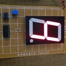
Step 5: Wire the Rotary Switch and Panel Meter


In this step, wire the rotary switch and panel meter for forming that perfect couple that permit to select the voltage wished and reading the voltage on the panel meter.
When you select the first scale with the rotary switch, you select 5Volt and can read 5Volt on the panel meter.
The first scale is defined with a line on the knob that is the first position in this type of switch while the second scale once selected with rotary switch will permit to read 9Volt on the panel meter.
Finally, the last scale or third position defined by the line marked on the knob we will permit to read 12Volt on the panel meter.
Step 6: Complete Your Project


In this step, complete your project. That is, connect the panel meter and rotary switch with the rest of the circuit.
Once you assemble the whole project, you need to plug in the AC/DC wall adapter/transformer into the power jack male.
Next, you have to plug in the AC/DC wall adapter/transformer into your home AC power supply.
Or, you can use a PCB smaller than that you are using now.
Step 7: Use DC 5V, 9V and 12V


In this step, you need to plug in the AC/DC wall adapter/transformer, with the rest of the circuit, into your home AC power supply.
If you want to read 5V on the panel meter, you should select the first position of your rotary switch.
If you want to read 9V on the panel meter, you will have to select the following scale of your rotary switch.
If you want to read 12Von the panel meter, you will select the third position of your rotary switch.
And complete your project!!!


