

Introduction: Tutorial for Arduino Mini DC Motor Driver Dual H-Bridge PWM Control (L293D)


Description
Tutorial for Arduino Mini DC Motor Driver Dual H-Bridge PWM Control module is ideal for use in battery-powered smart car, toy cars, robots. Supply voltage 2V ~ 10V, can drive two DC motors or a 4-wire 2-phase stepper motors, can achieve forward rotation or reverse rotation, it is possible to adjust the rotation speed. Each can provide continuous current of 1.5A, peak current up to 2.5A, thermal protection and can be automatically restored. Use of imported original chip, built-in low on-resistance MOS switch, minimal heat, no heat sink, small size, low power consumption, is ideal for battery powered.
Specification
- Module supply voltage: 2V-10V
- Signal input voltage: 1.8-7V
- Single working current: 1.5A
- Peak current up to 2.5A
- Low standby current (less than 0.1uA)
- Built-in common conduction circuit, the input terminal vacant, the motor does not malfunction
- Size: 24.7 * 21 * 7mm
- Mounting hole diameter: 2 mm
Step 1: Material Needed
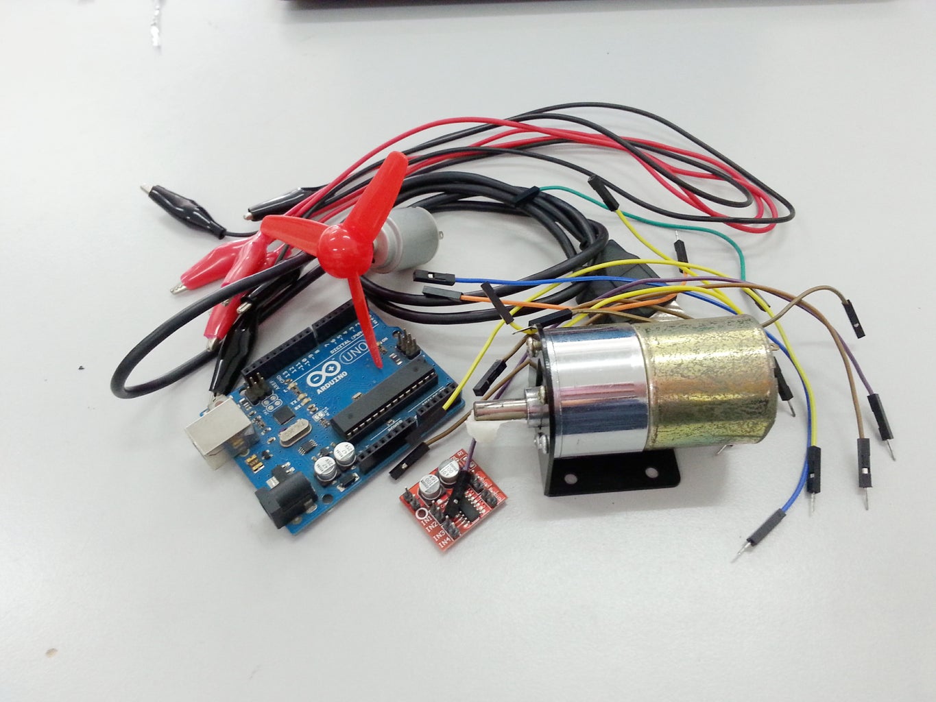
To do this tutorial, you will need to prepare all the following below:
1. Tutorial for Arduino Mini DC Motor Driver Dual H-Bridge PWM Control
2.Arduino Uno Board and USB
3. 2 DC Motors (any kind of DC motor can do)
4. Jumper Wires
5. Crocodile Clip (if needed)
Step 2: Pinout Details

- +/- to give power supply to the module and motor
- IN1 IN2 to control Motor A
- IN3 IN4 to control Motor B
- Motor A to be connected to DC Motor 1
- Motor B to be connected to DC Motor 2
Step 3: Hardware Installation

1. Tutorial for Arduino Mini DC Motor Driver Dual H-Bridge PWM Control to Arduino Uno
- + to VIN
- - to GND
- IN1 to D12 (OR you can change to any Digital Pin available on your UNO)
- IN2 to D11 (OR you can change to any Digital Pin available on your UNO)
- IN3 to D7 (OR you can change to any Digital Pin available on your UNO)
- IN4 to D6 (OR you can change to any Digital Pin available on your UNO)
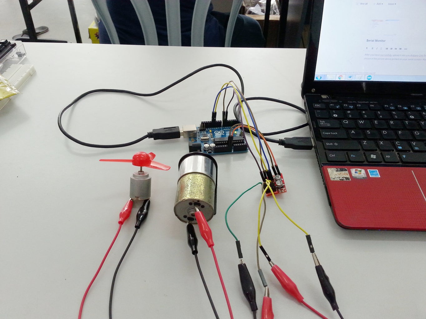
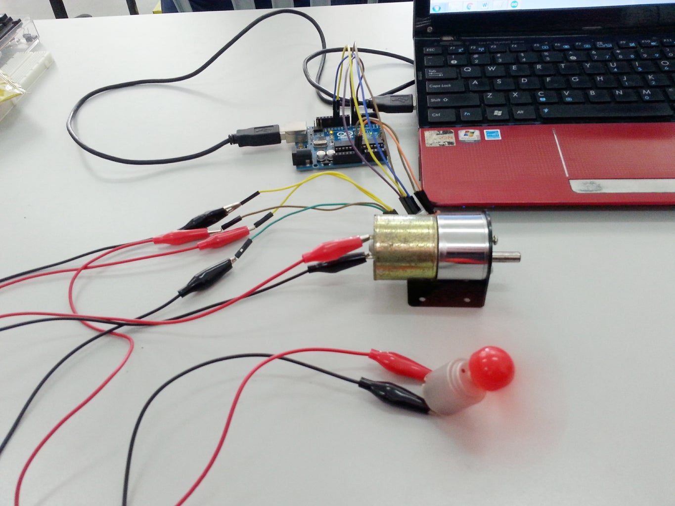
2. Connect your DC Motor to pinout Motor A and Motor B (refer picturefor help)
3. Connect your Arduino Uno Board to your computer using USB Cables.
Step 4: Sample Source Code

This is a sample source code for the circuit. You can download, open and and upload it into your Arduino Uno Board. Make sure to go to tools > Port & Board. Select the correct board (Arduino/Genuino Uno) and port (refer to your own port COM#) before uploading the code.
Attachments

Step 5: Serial Monitor


After you have succesfully upload it into you Arduino Uno Board. Go to tools > Serial Monitor and you will see as shown in the picture above printed on your serial monitor. Key-in number option (1, 2 OR 3) to start the operation!
Step 6: Result

- when user enter number '1', both dc motor start to rotate forward and serial monitor will print "Motor 1 forward, Motor 2 Forward".
- when user enter number '2', both dc motor start to reverse and serial monitor will print "Motor 1 Reverse, Motor 2 Reverse"
- when user enter number '3', both dc motor stop from rotating and serial monitor will print "Motor 1 Stop, Motor 2 Stop".
Step 7: Video
This video show how the DC motor function according to the sample source code attached in this tutorial.


