

Introduction: Tutorial of Rotary Encoder With Arduino
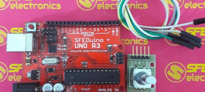


Rotary encoder is an electronic component capable of monitoring movement and position when rotating. Rotary encoder utilizes optical sensors that can generate pulses when the rotary encoder rotates. Application of the rotary encoder usually as a mechanical or robotic motion monitor can also be used for menu selection on the display. Rotary encoder has two outputs so that it can distinguish between negative (CW) and positive (CCW) rotation and also has a single button.
Step 1: Pulse Flow of Rotary Encoder

The pulse flow generated by the following rotary encoder is like the picture above.
Step 2: Pinout of Rotary Encoder

Explanation:
- GND --> GND
- + --> +5V
- SW --> button of rotary encoder when pressed
- DT --> Data
- CLK --> Data 2
One of the DT or CLK pins must be connected to the interrupt foot of Arduino Uno, or both of the DT and CLK are connected to the interrupt pin.
Step 3: Schematic
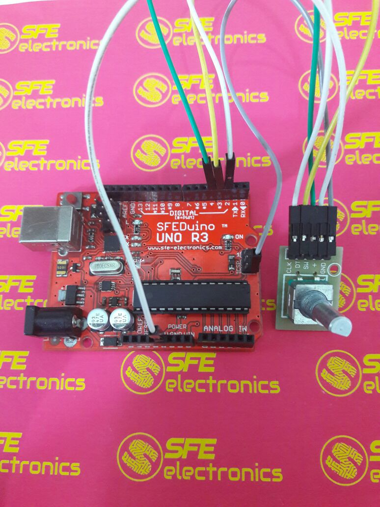
- GND à GND Arduino Uno
- + à +5V Arduino Uno
- SW à PIN 4 Arduino Uno
- DT à PIN 3 Arduino Uno
- CLK à PIN2 Arduino Uno
Step 4: Code

In the following tutorial, which will be used as an interrupt is PIN 2 of Arduino Uno, while PIN 3 is only used as a regular input.
#define encoder0PinA 2
#define encoder0PinB 3 #define encoder0Btn 4 int encoder0Pos = 0; void setup() { Serial.begin(9600); pinMode(encoder0PinA, INPUT_PULLUP); pinMode(encoder0PinB, INPUT_PULLUP); pinMode(encoder0Btn, INPUT_PULLUP); attachInterrupt(0, doEncoder, CHANGE); } int valRotary,lastValRotary; void loop() { int btn = digitalRead(encoder0Btn); Serial.print(btn); Serial.print(" "); Serial.print(valRotary); if(valRotary>lastValRotary) { Serial.print(" CW"); } if(valRotary {Serial.print(" CCW"); } lastValRotary = valRotary; Serial.println(" "); delay(250); } void doEncoder() { if (digitalRead(encoder0PinA) == digitalRead(encoder0PinB)) { encoder0Pos++; } else { encoder0Pos--; } valRotary = encoder0Pos/2.5; }
In line 10 of the sketch above is used to enable the interrupt of pin 2 Arduino Uno. In the "doEncoder" function is calculated from the rotary encoder. If the value of DT and CLK (pin interrupt of Arduino Uno) is the same, then the "encoder0Pos" variable will be incremented / added, in addition to that condition, the "encoder0Pos" variable is decremented.
Step 5: Explanation
ValRotary value is the value of the number of steps that have been running. ValRotary value is obtained from rotary sensor encoder reading value divided by 2.5. A value of 2.5 is obtained from the test, since one step of the rotary encoder may exceed 1, so divide by 2.5 for its value according to the perstep and also the addition of the read delay.
While on line 19 - 25 is a program to determine whether rotary rotary encoder CW or CCW. The explanation of lines 19 - 25 is when the current rotary encoder readout is greater than the previous rotary data then expressed as CW. Whereas if the current reading is smaller than the previous reading then it is stated as CCW.
Step 6: Output

1 = the start button value of the rotary when it has not been pressed


