

Introduction: "Twist Shield" for the Arduino


This little ‘Add-on’ board allows you to 'Twist' an existing Arduino Shield 90 degree from its original footprint
Attachments

Step 1: The Problem...
Have you ever finished a project and then realized you stopped one step too soon?
While plugging in various shields I have into the ‘Wing Tip Extensions’ I built I noticed an odd thing…display shields needed to be rotated 90 degrees to be of any real use…case in point the Adafruit RGB Display Shield shown, it works just fine but it’s orientation doesn’t work.
Back to the drawing board…or this case Eagle Cad.
Step 2: The Design...
The design is straight forward and is configured for a UNO R3 layout.
I couldn’t figure a way to do it with only one side so I made it into a double sided layout.
The via’s are larger than normal to accommodate drilling the holes.
No room for any icons…just a simple layout.
Attachments
Step 3: Etching
I’ll be honest here, I’ve never been very successful Etching dual sided PCB’s.
Usually the registration is off and the holes don’t line up…but this time I tried "booking" the PCB and had success.
I laser printed the top and bottom layers on to transparent sheets,
taped the bottom layer to a sheet of glass,
aligned the top layer over the bottom and made sure all the holes lined up. (Take your time)
taped only one edge of the top layer down so I could slip my Photo PCB between the layers like a book.
then placed another sheet of glass on top then using spring clamps I hold the ‘book’ together.
Exposed each side for 8 mins each, develop and etch as normal…I liked the results.
Step 4: Drilling
I would highly recommend the use of some kind of fence on your drill press to help keep the holes you are drilling for the headers straight as possible. Here I’m using a bar clamp for a fence in the photo.
The via holes, are just free hand.
Take your time to center them the best you can.
For the header holes I used a .80mm drill bit and for the via’s a .70mm drill bit.
Step 5: Vias by Hand
The vias are critical for this board to work.
I first bent ‘staple’ shapes out of scrap component leads.
Inserted the staples into the board and then soldered the legs first to keep them in place.
Clipped the top and straightened them so I could solder the other side.
Do this for all the via holes, keep an eye on your work for solder bridges.
Step 6: Male & Female Headers

You will need one 10, one 6 and two 8 pin Male & Female headers.
Solder the Male pins in first using your Arduino as a guide to help keep the pins in alignment.
Double check that you are soldiering on the trace side to make connection to your headers.
Step 7: Assembly
For this example I installed the Wing Tips and then added the Twist Shield on top
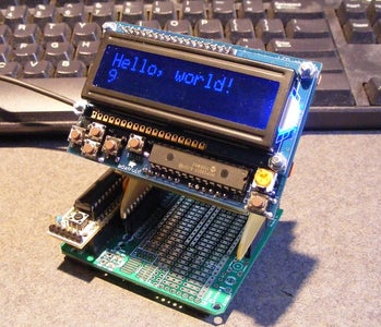
Installed the Adafruit RGB Display Shield and Voila!
It works! The display and buttons are correctly aligned now.
Step 8: Final Note
One interesting observation...
The ‘Twist Shield’ was designed to rotate the footprint Clockwise, but by mirroring the board layout during exposure you can make a Counter Clockwise twist board as well…two boards from one set of plans.

Participated in the
Arduino Challenge


