

Introduction: Twisty Balloon Pneumatic Actuator


Step 1: The Concept

Step 2: Building Valve Structure


First thing you'll want to do is get your valves set up.
You'll need a pressure valve (that opens the actuator to the pressurized line and lets it be pulled) and an exhaust valve (to let out the pressurized air and contract the actuator).
NOTE: Most valves have work better with a certain side exposed to the high pressure. In my case, the metal side needed to be attached to the pressurized side or I got too much leakage. I could never figure out which way the current was supposed to run on the valves (they worked both ways) so I just picked a direction and went for it.
The nubs on my valves were a little small so I stuck the connectors over them and used hot melt glue to make a nice seal.
The tee goes between the two valves and extends down to the balloon actuator. The pressure valve connects to the tubing being pressurized by the pump.
I recommend adding extensions to the wires already on the valves. Hook the two ground wires together so that you only have 3 wires extending from each valve set.
Step 3: Wiring


Because your current is way more than an Arduino pin can handle, you'll need to use some transistors.
The transistors I used could handle 1A of current. I wound up using 5 of them for this project. (one for each valve and one for the pump).
Each control wire needs to be connected to the transistor. In my case, the blue wire (collector) went to the positive terminal of the different components and the yellow wire (Base) went to the Arduino pin. The green wire (Emitter) is the input voltage.
There is a small voltage drop across the transistor (~.4V) so I used a 7v power supply so that the components would at least get their nominal 6v.
I mounted a bread board to the bottom of the frame where I could link all their components to their transistors and the transistors to the corresponding Arduino pins. See the example on the motor below.
Step 4: Building Frame


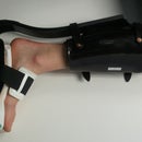
In order to extend, the springs need to be pulled by some other force. I used .5mm PETG that I lasercut on Ponoko.com. It was a little more floppy than I wanted it so I cut the length in half and glued the halves together with silicone.
If you wanted to use rigid legs, you would need to have a spring (or other strethed balloon) to pull against the actuating balloon.
To attach the legs to the acrylic frame. I glued legs in the slots first with epoxy but it proved too brittle so I used hot melt glue instead.
Zip ties are handy to mount the valve sets to your frame and the balloons to the central tee.
Because the air flow was so limited (and I had no accumulator), the balloons worked best when I inflated them one at a time. Otherwise, the more broken-in of the two would inflate while the other remained deflated.
Step 5: Programming

On the Arduino,
The easiest way I've found to program these complex series of valve firings is to use a function to define when to actuate each valve and then just break out of your loop at the correct times.
it looks something like this
void loop()
{
if (currrentTime == extendTime) Extend(leg);
if (currrentTime == retractTime) Retract(leg)
delay(1);
currentTime++;
}
I've attached my actual Arduino sketch for more clarity
Attachments

Step 6: The Future

I think this is a valuable platform for small robots that need long, linear strokes. With a little more research and cost, a higher pressure model of the same thing could be developed. By making the bellows into a "pull-type" actuator, you can use it in place of muscles in bio-inspired robots.
If you use this concept, or a derivative in a future build, let me know! you can find me at WyattFelt.com
It's fun to see how others take your ideas and make them better. When I made Posterbot in 2007 little did I know that it would inspire Printbot which is now in iRobot's Hall of Fame.

Participated in the
Arduino Challenge

Participated in the
Robot Challenge


