

Introduction: USB Volume Control and Caps Lock LED - Simple, Cheap, Extensible


I'm not the first person to publish an Instructable for a USB volume control, but I think this one is about as simple and cheap as it gets, and at the same time can be extended at minimal cost to various other functions such as:
- Mute, Play, Pause and various other media buttons
- Keyboard LEDs such as Caps Lock, Scroll Lock and Num Lock (a kana LED is also defined for Japanese users)
- Application launch buttons such as browser, email, calculator etc
- Browser navigation and other application control buttons
- Gamepad buttons
- System buttons for functions such as Sleep, Hibernate, Wake, Power down
- Laptop screen brightness (Windows 8/10 only)
- Mouse buttons and movement
and many more, subject to support being provided by your operating system. Mine implements the volume and mute functions (mute by pressing the knob) and the 3 main keyboard LEDs.
Have you ever clicked on a Youtube video and then fumbled for the volume control buttons when it started playing far too loud? Older laptops used to have a physical volume control but this is rare on newer ones and on desktop computers, which is why I wanted to build this.
And how many times have you carried on typing long after accidentally hitting Caps Lock, maybe on a scrabble tile type keyboard with the Caps Lock button a bit too close to the A key, and maybe having an inadequate Caps Lock light or no light at all? That was the other reason.
I assume you'll probably use a different box and so I leave most of the mechanical details to you, Other Instructables may give you a more aesthetically pleasing product using computerised manufacturing but my objective is to concentrate on the electronics.
Step 1: What You Need

This project is built around the Arduino Pro Micro (5V version), available from Far Eastern suppliers for £2 - £3. Other ATMega 32u4 based devices could be used, but not ones based on the ATmega328 such as the Nano or Pro Mini.
You also need a 5-pin rotary encoder, which you can probably find for £0.99, and a knob to suit.
The remaining parts you may have lying around:
- Micro USB cable
- LEDs (if required) and a 330Ω resistor for each LED
- 1 tactile push button switch for reset - not normally needed (see later)
- Additional tactile push buttons if required for additional functions (search for PBS-33b for a type I've successfully used on another project)
- A couple of scraps of stripboard
- Small project box
- Connecting wire, soldering iron, solder, wire strippers and cutters etc.
Step 2: How It Works

You may have noticed that a lot of USB keyboards have multimedia keys such as volume up and down, mute, play/pause. Some also have application keys such as email, browser or calculator, and some even have system keys such as sleep and hibernate.
The normal alphanumeric and arrow keys don't send a character to the computer but a scan code, representing the key position. The existence of multimedia and other keys implies that these too have scan codes, so I reasoned it should be easy enough to program an Arduino to send these since the Leonardo and Pro Micro can emulate a keyboard or mouse through their USB port. But I soon hit a snag.
I quickly discovered that the Arduino Keyboard library only allows you to send the keys found on the original standard IBM PC keyboard. Multimedia and system keys comprise completely separate sets which are not supported. In the same way, mouse movements and clicks are another set, supported by the Arduino Mouse library. However, amongst those sets there is a huge array of functions defined, though not all are implemented by Windows or other operating systems.
Digging into it to the point where I was almost ready to start enhancing the Keyboard library, I found it had already been done. The optional HID-Project library provides everything you could possibly want.
Step 3: Construction


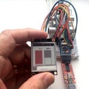
I used a box I've had for years, left over from a long since forgotten project that never got completed. It has dimensions 50x50x20mm and probably came from Maplin, unfortunately no longer trading in the same form.
But you will probably be using a different one, so I leave all the mechanical construction details to you. You can see well enough from the pictures how I built mine.
The Arduino and a push-button are mounted on a piece of stripboard cut to fit the box. (The push-button is needed to reset the Arduino for programming.) The stripboard is used more to mount them than to wire them up. A couple of short pieces of wire passing through unused Arduino pads and through the stripboard, soldered to both, hold the Arduino on place. The stripboard is held in place in the box with a couple of blobs of hot melt glue.
The LEDs and resistors are mounted on a second piece of stripboard. The LEDs are a tight push fit in the holes they fit in and need no other fixing.
Step 4: Wiring It Up

If you like, you can test it out on a half-size breadboard. Alternatively use the diagram to solder it up.
Use stranded wire. I used a couple of scraps of rainbow ribbon cable, which kept the wiring reasonably neat, and the different colours made it easy to see which wire was going where.
Step 5: Programming
If you don't already have it, you need to download and install the Arduino IDE.
In your Arduino folder (by default under Windows this is in My Documents) create a folder called VolumeCtrl. Copy the file VolumeCtrl.ino into this folder. Now launch the Arduino IDE and locate the sketch VolumeCtrl in your sketchbook.
You will need to install the HID-Project library. This is easy:
Click on Sketch - Include Library - Manage Libraries. In the Filter box, type HID-Project. This should give you Extended HID Functions for Arduino. Click the Install button. That's all there is to it.
You will also need to ensure you have the Pro Micro board definition installed. If you haven't, don't be tempted to try a different one - you'll see why in a moment.
Click on Tools - Board - Board Manager. Check whether Sparkfun Pro Micro is already shown. If not, in the Filter box, type Pro Micro. Select and install the package which includes the SparkFun Pro Micro in its list of supported boards.
Now, under Tools - Board, select SparkFun Pro Micro, and under Processor, select ATMega32u4 (5V, 16MHz).
Note: if you try to program the device with the wrong board selected you will likely kill the bootloader! (If you already have done, keep reading.)
Under Tools: Port you will probably see several COM ports. Check which one only appears when the Pro Micro is plugged into a USB port. If your Pro Micro has an old bootloader it might detect and display it as Pro Micro.
There are 3 ways of programming the Pro Micro, and before proceeding you must decide which you are going to use:
- USB programming through the Pro Micro's USB port
- ISP programming using an AVR ISP programmer
- Programming using another Arduino as ISP programmer.
Early Pro Micros tended to be a little temperamental to program, and you will require the optional reset button but later ones have a much better bootloader, for which the first method should work reliably. All three methods are described in the next steps.
Attachments

Step 6: USB Programming
Programming through the Pro Micro's microUSB port depends on having a working bootloader. If you've already killed it you will need to use method 2 or 3 described in the next step.
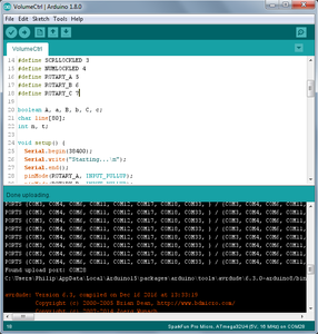
Connect the Pro Micro to a USB port on your computer. On the Arduino IDE, click Sketch - Upload (not Upload using Programmer). Watch the black panel at the bottom of the IDE.
When compilation and linking are complete you will see it scanning COM ports looking for the Pro Micro. If you have a modern bootloader and you selected the right COM port in the previous step, it should program your Pro Micro, with a progress bar consisting of "#" characters.
If not, double-check you selected the right COM port.
If you're sure you have, when you see it scanning COM ports, quickly do a double-press on the reset button. It should then be programmed.
As soon as it's programmed it should reset and start working as a volume control. It will flash the caps lock, scroll lock and num lock LEDS (if you're using them) to show it's working.
Step 7: ISP Programming

USB programming depends on having a bootloader pre-installed. This is just another program pretty much like one you might write yourself. ISP programming, on the other hand, uses dedicated logic on the chip itself, and is how the bootloader gets loaded by the manufacturer.
You can get an AVR ISP programmer quite cheaply (this is method 2). Make sure it's one the IDE supports. The programmer comes with a 6-pin connector. Use your favourite search engine to search for "avr isp pinout" to identify the pins. Fit an ISP header to the stripboard and wire it up to the Pro Micro as follows:
| ISP Pin | Pro Micro pin | |
| 1 | 12 | MISO |
| 2 | Vcc | |
| 3 | 13 | SCK |
| 4 | 11 | MOSI |
| 5 | 10 | RST |
| 6 | Gnd |
Under Tools - Programmer you need to select the type of programmer you are using.
Alternatively you can use another Arduino to do the same job (method 3). This can be a cheap Nano, or an even cheaper Pro Mini with an FTDI USB/serial adapter.
In the IDE, click on File - Examples - ArduinoISP. A block comment at the front of the sketch tells you how to wire it up. This depends on whether your additional Arduino has an ISP header and whether you use it. If not, you will have to uncomment the line
#ifdef USE_OLD_STYLE_WIRING
On the Arduino used for programming, connect a LED and 330Ω from each of pins 7, 8 and 9 to ground. These indicate Programming Mode, Error and Heartbeat. Connect other pins to the ISP header you fitted, or directly to the Pro Micro. Program it with the ArduinoISP sketch, and under Tools - Programmer select Arduino as ISP.
Step 8: Adding Additional Functions
The USB HID (Human Interface Device) class allows a wholerange of controls, matching the different types of human interface device. The HID-Project library used here makes many if not all of them easily available.
Examine the sketch VolumeCtrl. The push-button function on the rotary encoder is defined as ROTARY_C. You can define further buttons if you like in the same way and use the same logic to detect button pushes. Instead of the line Consumer.write(MEDIA_VOL_MUTE); you write a similar line to perform the required function.
In the IDE, click File - Examples - HID-Project for examples showing how the different types are used. The full range of controls for each type is given in a header file located in libraries\HID-Project\src\HID-APIs in your Arduino folder (which is normally in My Documents).
The examples and header file for each type are given below.
Consumer:
- Hundreds of controls are available including a full range of media player controls, screensaver, application launch (email, browser, calculator), browser navigation and media centre controls.
- Example: Consumer
- List of controls: ConsumerAPI.h
System:
- System controls such as sleep, hibernate, power down, undock, wakup, primary/secondary display controls and menu navigation.
- Example: System
- List of controls: SystemAPI.h
Gamepad:
- 32 Buttons, 6 Axis, 2 D-Pads
- Example: Gamepad
- List of controls: GamepadAPI.h
Keyboard:
- Several variants are available: a boot keyboard understood by the BIOS, an improoved keyboard allowing text strings to be sent, and a keyboard allowing n-key roll-over.
- Examples: BootKeyboard, ImprovedKeyboard, NKROKeyboard
- List of keys: ImprovedKeylayouts.h
Keyboard LEDs:
- Reports the Caps Lock, Scroll Lock and Num Lock LEDs and some more you never knew existed.
- Example: KeyboardLed
- List of LEDs: ImprovedKeyLayouts.h
Mouse:
- Two variants, one pretty much the same as the standard Mouse library, and another allowing movement to an absolute position.
- Examples: ImprovedMouse, AbsoluteMouse
- List of controls: MouseAPI.h
Laptop screen brightness
- Supported on Windows from Win 8 only (see ref) - Mac/Linux support unknown.
- Use the same code as for the volume control but replace MEDIA_VOL_UP and MEDIA_VOL_DOWN by 0x006F and 0x0070 respectively.
- Works for laptop (or mobile device) screen only (though I haven't tried it). Won't work for an attached monitor or projector as neither VGA or DVI/HDMI interfaces support it.
Further documentation can be found at https://github.com/NicoHood/HID/wiki

Participated in the
Arduino Contest 2016


