

Introduction: Ultimate RGB Propeller Display


Like many I find something extremely satisfying about watching light displays in awe. From bonfire night fireworks to pretty in game graphics and even an 8x8x8 RGB LED cube I built back in 2013.
I have had many attempts at a reliable RGB propeller clock over the years and though I have had many prototypes up and running they never seemed to stay working for long or be good enough for me to shout about. This is my attempt at a stable design that should last for a long time.
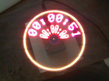
The display features 24 x RGB LEDs, provides a flicker free image to the human eye and is powerful enough to display and manipulate simple 3D meshes in real time. Also included are timing mechanisms to drive a clock and synchronization mechanisms to keep the image stable independent of the motor speed.
Step 1: Propeller Display Theory


A propeller display is made up of a single row of LEDs that are spun by a motor. As the motor spins the LEDs the LEDs switch on and off at high speed allowing a stable image to be displayed within the arc of the LEDs.
A micocontroller brain is used to switch the LEDs on and off at the right moment to draw the image. As the circuitry spins around an onboard sensor such as a hall effect or IR beam breaker is used to synchronize the microcontroller and keep the displayed image static.
In my experience as an embedded engineer the tricky part is not the circuitry but the mechanics. Mainly picking the right motor for the job and creating a way of passing power to the circuity as it spins.
Step 2: The LED Circuit

The LEDs are driven using a simple buffering system using cheap and cheerful 74 series octal buffer chips. There are some nice LED driver chips available now but if you know what your doing and have plenty of processing power in your microcontroller then these are not a necessity.
The LEDs I used are very small SMD type common anode LEDs I bought from Farnell. They were expensive but come complete with a lense and look very good lit up. They are also very small, I originally tried a display of 32 LEDs using a much bigger LED and though this worked very well it was a bit too large to be spinning at high speed without any safety cage.
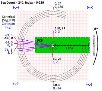
To drive the LEDs I use 8 data pins from the microcontroller and a clock pin. The 8 data pins are connected to the input of the first octal buffer IC and the cathodes of the first 8 LEDs. The 8 outputs from the first buffer IC are then fed to the 8 inputs of the second buffer IC and the cathodes of the second 8 LEDs. The clock signal is fed to all of the buffer ICs so that they all clock together at the same time. Using this technique you get (8 + 1) * 8 = 72 bits of control or 72 / 3 = 24 RGB LEDs. If 11 buffer ICs were used then the number of RGB LEDs goes up to 32.
The LED anode pins are all connected together and then fed to the drain pin of a logic level P channel FET. This allows all the LEDs to be switched off as we clock out the data. Without the FET you tend to get some light smeared over the inner display when the outer display is lit which is best avoided. This smearing effect is shown in the image.
The red LEDs have a lower driver voltage than the green and blue channels so the resistors are there to allow the colour intensity to remain uniform for all three colours.
Of course you don't have to use RGB LEDs, normal LEDs will work just as well and give you 3 x the resolution for the same number of control signals. I'm just a sucker for the pretty colours.
Step 3: The Motor Driver Circuit
The motor driver is made up of two parts.
1) The circuit to drive the motor to make it spin.
2) The circuit to pass the voltage to the display circuitry.
The circuit to make the motor spin is very simple and can be achieved with a simple transistor and diode. The transistor is driven using the PWM output from a second microcontroller or can simply be connected to a DC voltage. The DC voltage should be chosen so that the display will run at around 60 cycles per second when up to speed to try and best eliminate any visible flickering.
The circuit/mechanics to pass the voltage to the rotating display circuitry is a bit more complicated.
Step 4: Motor Mechanics - the Complicated Way

Background, you can skip this step if you like.
One method I have used which works is to use the DC motor itself to pass through the current to the display circuitry. Inside the motor is a mechanism to allow the rotating coils of the motor to be powered from the motors fixed terminals using sprung contacts which hug to a commutator fixed to the motor shaft. By wiring into the motors coils and bringing the wires through the front of the motor we can supply power.
Start with a cheap DC motor, I used a 28 pence motor from Rapid.
Bend up the metal lugs which hold the plastic rear plate in place and then remove the plastic being careful not to damage the contact springs.
Remove the motor spindle.
Grind the front axle mount from the motor using a grinding stone until you are left with a sizable hole in the front of the casing.
3D print a mounting for a 0612 ball bearing that also slots over the front of the motor housing.
Laser cut a tiny plastic disk that will fit tight inside the bearing with a central hole for the motor axle.
Add extra holes in the disk to allow three wires to come out the front of the motor case.
Solder three thin insulated pieces of wire to the three phases on the motor and then feed these wires through the hole in the motor casing and through the three holes in the laser cut disk.
Re-assemble the motor taking care of the contacts again and bend the metal lugs back in place.
Check the motor spins freely.
This works and was my prefarred method for a time but there are a number of key downsides.
1. All of the current for the LEDs will be supplied via the motor contacts meaning they will wear much more rapidly.
2. Its a fairly big job to do one motor
3. The motor has to be spinning for the display to power up meaning troubleshooting can mean dismantling
4. The motors speed cannot easily be controlled without also effecting the voltage fed to the display circuit
5. The display circuit needs additional 6 additional diodes to form voltage rectifier bridges meaning further voltage drops in the supply rails
Step 5: Motor Mechanics - the Frustrating Way
Background, you can skip this step if you like.
Another way to drive the display electronics is to create a generator, As the motor spins the display circuitry this then spins a large coil which passes perpendicular to a series of magnets. The spinning coil generates it's own power.
This is demonstrated in a lot of good prop clock designs and is known to work well long term as seen in a recent article from Elektor but for me it's too much effort. I even have my own coil winder gizmo and for me it's still too much like effort.
There is also the downside that the motor not only has to spin the display but also generate enough torque strength to create enough electrical power to drive the display.
I needed something simpler...
Step 6: Motor Mechanics - the Simple Way
To make life as easy as possible I went with the slip rings approach.
Two signals are required by the display circuitry, power and ground.
The power is fed through to the display circuitry using the motor shaft and motor housing. The controller PCB fits onto the 2mm motor shaft and solders on to give a nice electrical connection. A multi-strand wire is held against the motor housing using the 3D printed mechanics. The current is transferred from the motor body to the motor shaft via the motors metal bushing.
The ground is fed through to the display using a slip ring technique. A fixed metal plate which is held next to the spinning circuitry. The circuitry then has spring contacts which make contact with the metal ring as the display rotates. I started by using a thrust bearing with inner dimensions bigger then the width of the DC motor. This provided superb electrical contact but also made a racket when spinning. So I removed the rotating parts of the bearing and simply used one side. The other side of the connector I made using a 3D printed part and some multi stranded wire. The wire touches the metal ring in three places to try and ensure a good electrical contact at all times. The side of the thrust bearing has a nice rounded groove that helps to keep the wire in play on the metal.
Advantages I found to this technique
1) It works well assuming you line up the motor and plate nicely.
2) It seems to last long term
3) It is easily serviceable if needed
4) The display can be powered without powering the motor
5) The motor speed can easily be controlled using PWM etc
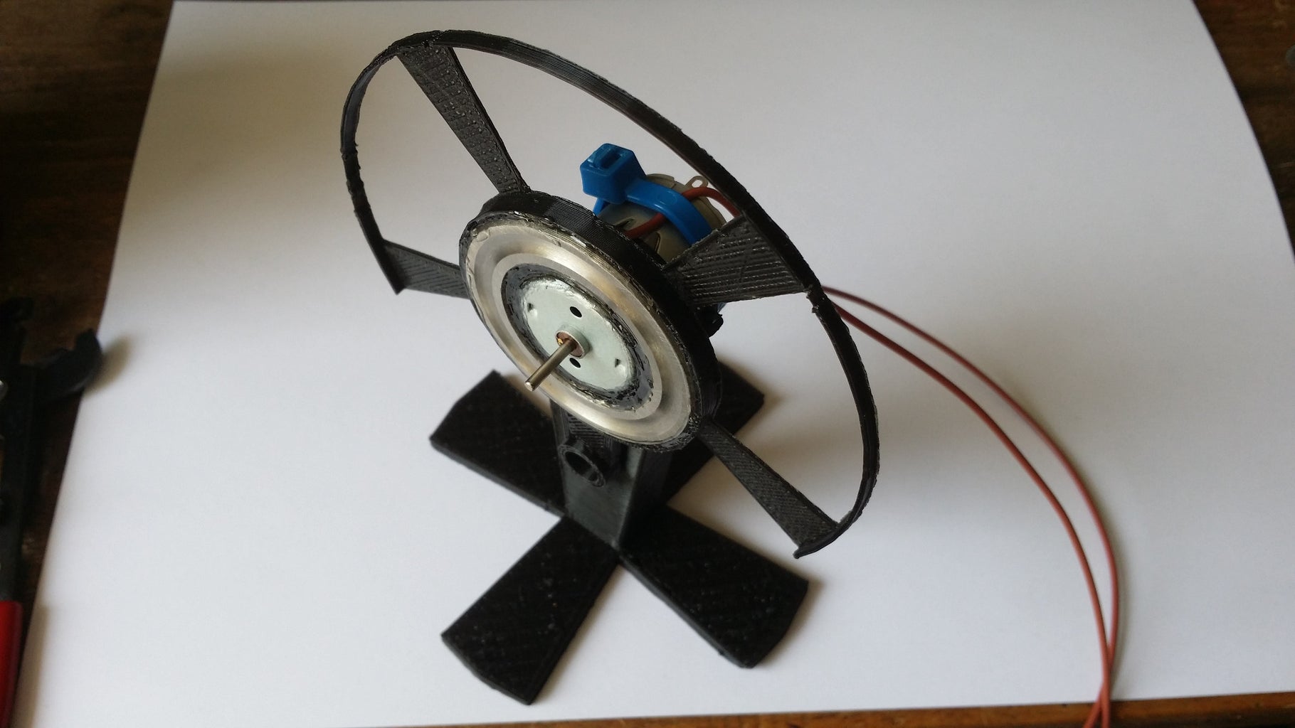
Step 7: 3D Printing the Parts
There are three 3D printed parts required for this build.
1) The stand to hold the DC motor.
2) The guard rail, synchronization magnet and slip ring housing.
3) The display PCB slip ring contact housing.
Each of the parts was printed using PLA at 0.3mm layer height without support material.
Note the parts are optimized for my RepRap printer so you may have to tweak the CAD to get a nice tight fit.


Step 8: Assembling the Parts


To begin the assembly I first removed the insulation from about 1 inch of my multi-strand wire and inserted this through the hole in the 3D printed guard piece. I splayed out the strands of the cable and then snapped the side of the thrust bearing into place ensuring it was as flush as possible with the 3D printed surface.
I then inserted the motor and used a CD to get the front of the motor perfectly lined up with the metal bearing plate. I took some time doing this until it was perfect and then used good super glue on both sides of the 3D print to fix the motor and bearing plate in position. Just be careful not to get any glue into the motor or on the contact part of the bearing plate.
I then slid the other 3D printed slip ring part over my display PCB, lined it up so it was central to the motor axle hole on the PCB and glued this in place.
Once everything was dry I added the multi-strand wire to the slip ring part and glued in place before connected through to the power pads on my PCB. I pushed the PCB into place on the motor axle and again took time to get this leveled correctly before soldering the PCB directly onto the motor shaft.
Another piece of multi-strand wire is added to the underside of the motor bracket on the 3D printed stand and the motor held in place to the stand using tie bands.
Additional wires were then soldered to the motor terminals giving me 4 wires in total, 2 for the motor and 2 for the display electronics.
Step 9: The Software

I made the software a number of years ago using Flowcode 4. I wrote versions for AVR/Arduino and dsPIC. The current design uses the dsPIC for the additional processing power but both are viable options.
I wrote the software as a custom C component and then used Flowcode to call the functions from the library.
There is a discussion surrounding the current software available from the Flowcode forums:
http://www.matrixtsl.com/mmforums/viewtopic.php?f=...
The compiled firmware is loaded onto the device using a Pickit3 programmer via the 6 way ICSP socket.
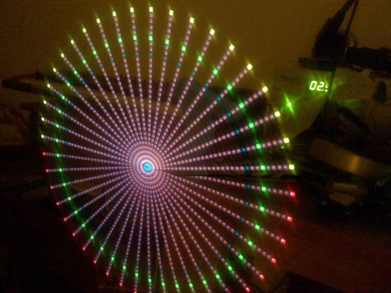
I have started to redo the software using Flowcode 6 which is vastly more powerful and will allow me to create a fully working simulation to help speed up time creating animations etc. This is currently shared on the link below and the simulation so far is shown in the image.

Step 10: Adding Extras, IR, SD Card
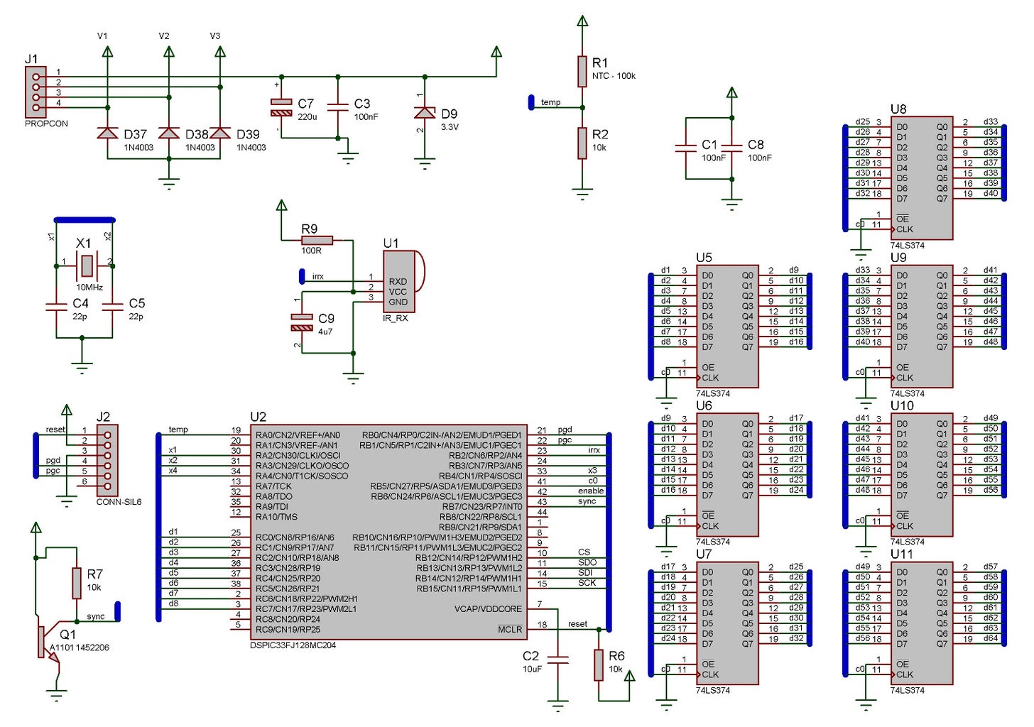

On my display circuit I decided to add some extra features. The full schematic for my LED display circuit is shown in the attached.
A filtered IR receiver to allow me to do things like set the time and play simple games using a standard TV remote (circular space invaders anyone?).
A micro SD card socket to allow me to store sprites, animation scripts and anything else too big to fit into the microcontrollers limited memory.
At one point I tried a microphone so I could do audio frequency based visualizations but the noise from the spinning display tended to overpower the ambient sounds.
A speaker and battery backup RTC might also be nice additions to allow for alarm functionality.
Bluetooth or Wifi would also be a good option now that simple embedded modules can be found for very low cost direct from China.
Some people have multiple arms of LEDs to increase the refresh rate without having to increase the motor speed. Using three sets of LEDs the display would also spin a lot more stable than compared to two or one and so not have to be finely balanced with technical blue tack.
Step 11: Ordering Circuit Boards
The motor driver circuitry can be done using something off the shelf such as an Arduino with a motor driver shield or proto shield. The display circuitry however will likely have to be custom made for your specific components.
To create your own circuit board for the display you will need some good PCB design software such as Eagle or Proteus. Software with a working and efficient auto route function will help massively in squeezing in all the signal traces.
Your PCBs can be bought online from vendors such as Eurocircuits who offer fairly good prices on low quantity PCBs and have tools to help you check your design before you place the order.
The cost is based on board size so the smaller the board is the cheaper it will be.
For my latest batch of PCBs I had a number of circuit boards professionally made up with components. If anyone would like to own one of these boards then please let me know. It's first come first served i'm afraid. I'll also throw in a motor, some wire and even the 3D printed parts and thrust bearing side if needed. The CAD file is attached should you wish to order the unpopulated PCBs directly.
If your making your own boards then you can order your PCB with a surface mount mask which will allow you to apply solder paste and bake your board in a toaster over or reflow oven if you have one. I have baked my SMD boards for years using a £10 toaster oven from eBay and there are lots of tutorials out there on how to do it well.
Attachments
Step 12: The Working Prototypes


Shown are a couple of shots of the various prototypes through the years.
Step 13: The Finished Design


Thanks for viewing my instructable I hope you have enjoyed the journey and if you're planning on building a propeller display then let me know how your getting on.
By playing around with the slip ring I managed to make the display run very quietly as can be seen in the video, as you can see my phone is doing some fairly bizarre things like going in and out of sync with the LED PWM. To the human eye the display is static.
I'm currently using a 16F1937 with PWM control connected to a motor driver to drive the DC motor. The motor speed is then controlled via a potentiometer. This is currently a large E-blocks setup but can easily be miniaturised by making a second PCB. When I get around to this I will post an update.
The LED PCB is currently power by a DC bench supply set to 3.6V to take account for the diode voltage drop. Again this will be added to the motor driver PCB.
The display has been quickly balanced with a blob of blue tack but with a bit more time I could do a far better job which should allow me to run the motor even faster without vibration. Then hopefully my phone might take a better photo.
Now to crack on with some animations and get the IR running so we can play some games...


