

Introduction: Ultrasonic Ballotbot


Credible elections are a cornerstone of democracy. Allegations of vote fraud and ballot box stuffing can call into question the credibility of an election. Without evidence to prove or disprove allegations, voters may not have public confidence or in the official results. Sensors affixed to the doorjamb and inside the ballot box could be used to passively collect data on voter participation, specifically when a voter enters a polling station and casts a ballot. Such data could help to prove or disprove allegations of fraud and promote confidence in the process to the degree warranted.
For the purposes of detecting a ballot (and other non-heat emitting objects) an ultrasonic sensor works well. An ultrasonic sensor uses echolocation to detect an object. It transmits an inaudible “ping” that bounces off an object and returns an echo. Applying principles of physics, you can measure distance by calculating how long it takes for sound to travel to and from the object. Various types of ultrasonic sensors can be found in factories, hospitals, submarines, and self-driving cars.
In this tutorial, we’ll use a short-range ultrasonic sensor that is low-cost and highly accurate. To create our ultrasonic ballotbot, we’ll connect the sensor to an Arduino Uno microcontroller and program it to transmit a ping every second for a distance measurement. We’ll connect the sensor to an Adafruit data logging shield that has an SD card slot and a real-time clock to be able record and timestamp measurements that indicate a ballot has been cast (< 10cm). We’ll solder all the components together and test the prototype using a battery pack to power sensor and some velcro strips to affix the sensor and battery pack under the ballot box lid.
Step 1: What You Need


For basic ultrasonic circuit:
SainSmart HC-SR04 Ranging Detector
To record and timestamp data:
Adafruit Assembled Data Logging Shield
To connect the shield and sensor:
To test the prototype:
AA battery pack w/DC barrel jack (and batteries)
ballot box (a plastic storage container will do)
Note: if you’re brand new to Arduino, you should seriously consider theArduino Starter Kit, which comes with a microcontroller board, serial USB cable, jumper wires, and breadboard. You’ll also need to download the Arduino IDE
Also note: The Adafruit Data Logging Shield should come with a CR1220 3V coin cell battery and stacking headers
Step 2: Build the Circuit (sensor, No Shield)
Let’s build a circuit with just the Arduino and ultrasonic sensor to make sure it works. Make sure the Arduino is not connected to your computer or any other power supply.
The HC-SR04 has four connector pins:
1) VCC (power )
2) TRIG
3) ECHO
4) GND (ground)
Place the HC-SR04 sensor on the breadboard and connect these four pins to the Arduino pins using your jumper wires. Use the circuit illustration as reference.
Connect the Arduino 5V pin to HC-SR04 VCC pin
Connect the Arduino GND pin to HC-SR04 GND pin
Connect the Arduino pin 7 to HC-SR04 TRIG pin
Connect the Arduino pin 8 to HC-SR04 ECHO pin
Note: it doesn't matter where you place the sensor on the breadboard as long as each pin is placed in a different row (on a breadboard, the power rails are connected north-south, the terminal strips are connected east-west in each row).
Attachments

Step 3: Upload the Code (sensor, No Shield)

Connect the Arduino to your computer via the USB Serial port. Open the Arduino IDE and enter the following code in a new sketch. Alternatively, you can download the file from the ballotbots GitHub repo.
int trig = 7;			//declares Arduino pin 7 as “trig”
int echo = 8; 			//declares Arduino pin 8 as “echo”
float v = 331.5 + 0.6 * 20;	//calculates speed at 20 deg c

void setup() {
	Serial.begin(9600);	//starts Serial Monitor 9600 baud
	pinMode(trig, OUTPUT);	//initializes trig as output pin
	pinMode(echo, INPUT);	//initializes echo as input pin
        delay(5000);            //wait 5 sec for sensor to settle
}

float distance() {
	digitalWrite(trig, LOW);		//set trig pin
	delay(500);				//wait 500ms
	digitalWrite(trig, HIGH);		//initiate a ping!
	delay(500);				//wait 0.5 seconds
	digitalWrite(trig, LOW);		//reset trig pin
	float range = pulseIn(echo, HIGH);	//when echo received
	float t = range / 1000.0 / 1000.0 / 2;	//echo range into sec
	float d = t * v;			//time * velocity
	return d * 100;				//translate into cm
}

void loop() {
	int d = distance();			//d = distance function
	Serial.print(F("distance in cm: "));
        Serial.println(d, DEC);                 //print distance reading
          if (d < 10) {                         //if distance < 10cm
	     Serial.println("ballot detected");
          }
}
Verify, save, and upload the sketch to the Arduino.
Once it is done uploading, open the Serial Monitor (make sure baud rate is set to 9600). After five seconds have passed to allow the sensor to settle, you should see distance readings every second.
When you place an object in within 10 centimeters of the ultrasonic sensor, you should get the distance followed by a reading of “ballot detected” on the next line.
Step 4: Set Up the Data Logging Shield

To be able to use data logging shield, you need to do a bit of setup work including:
1. Soldering headers onto the data logging shield
2. Downloading libraries to use the shield with Arduino
3. Calibrating the real-time clock
4. Formatting the SD card (if card is not pre-formatted)
First, you solder headers onto it to be able to connect it to the Arduino. Follow the steps in the tutorial on the Adafruit blog to solder the headers on to the shield.
Second, you need to download the Adafruit real-time clock (RTC) and SD card libraries. You will need these libraries to enable the shield to work with Arduino.
Download Adafruit RTC Library
Download Adafruit SD Card Library
Once you have downloaded the RTC library, unzip the zip file, rename the unzipped folder “RTClib”, and install it in your Arduino directory. Follow the same process for the SD Card library and rename the unzipped folder “SD”. If you haven’t installed a library before, this Adafruit tutorial shows you how on Linux, OSX and Windows. Once you have installed the libraries, you will need to restart the Arduino IDE.
Third, you need to calibrate the real-time clock. To calibrate the clock, insert the CR1220 3V coin cell battery into the battery holder. Put the shield on the Arduino, connect the Arduino to your computer via the USB A-B cable, and open up the Arduino IDE. In the Arduino IDE, open the ds1307 file (go to File > Examples > RTClib > ds1307) and - if they're not already removed - remove the comment marks (//) from:
//rtc.adjust(DateTime(F(__DATE__), F(__TIME__)));
so it reads:
rtc.adjust(DateTime(F(__DATE__), F(__TIME__)));
and can be seen by the compiler. Once you have removed the comment lines, save the example file and upload it to the Arduino. Open the Serial Monitor, make sure the baud is set to 57600, and you should see the current date and time displayed.
Finally, if you are not using a pre-formatted SD card, you will need to format it before you can use it. If so, insert the SD card into your computer, download the SD card formatter for your operating system and follow the instruction manual.
Step 5: Build the Circuit (sensor and Shield)


Gently remove the shield from Arduino. Slot the four HC-SR04 ultrasonic sensor pins through four pads at the front edge of the prototyping area in the shield. Solder jumper wires to the HC-SR04 pins to pads on the shield:
Solder shield 5V pad to HC-SR04 VCC pin
Solder shield GND pad to HC-SR04 GND pin
Solder shield pad 7 to HC-SR04 TRIG pin
Solder shield pad 8 to HC-SR04 ECHO pin
Note: there are no traces between pads in the prototyping area so you need to solder the jumper wires directly to the HC-SR04 pins. Be careful not to accidentally forge a connection between two HC-SR04 pins while soldering. This can cause the sensor to not work properly or, worse, cause irreparable damage to the board, shield and sensor. You should use a solder sucker to remove solder that connects pins by mistake.
Step 6: Upload the Code (sensor and Shield)

Put the Adafruit data logging shield with the soldered ultrasonic sensor on the Arduino. Make sure the coin cell battery and SD card are inserted in the shield.
Connect the Arduino to your computer with the USB A-B cable and open up a new sketch in the Arduino IDE. Paste the following code in the new sketch. You can also download the file from the ballotbots GitHub repo.
#include <Wire.h> //for I2C
#include <RTClib.h> //for RTC #include <SD.h> //for SD cardconst int sdpow = 3; //power for SD const int sdpin = 10; //default tx for SD const int rtcpow = A3; //power for rtc const int rtcgnd = A2; //ground for rtc int trig = 7; int echo = 8; float v = 331.3 + 0.606 * 20; int i = 1; //start for Serial count++ int x = 1; //start for SD card count++
RTC_DS1307 rtc; //initialize use of rtc
void setup() { Serial.begin(9600); pinMode(sdpow, OUTPUT); digitalWrite(sdpow, HIGH); pinMode(sdpin, OUTPUT); pinMode(rtcpow, OUTPUT); digitalWrite(rtcpow, HIGH); pinMode(rtcgnd, OUTPUT); digitalWrite(rtcgnd, LOW); pinMode(trig, OUTPUT); pinMode(echo, INPUT); delay(5000); if(!SD.begin(sdpin)) { //if card comm fail Serial.println("Card Fail"); return; } Serial.println("Card Success"); //else
Wire.begin(); //start I2C comm rtc.begin(); //start rtc comm
if(!rtc.begin()) { //if rtc start fails Serial.println("RTC Fail"); return; } Serial.println("RTC Success"); //else //open SD card, create & open csv, write & close file: File logFile = SD.open("counter.csv", FILE_WRITE); if(logFile) { String header = "label,reading,date,time,value,unit,cm"; logFile.println(header); logFile.close(); Serial.println(header); //also print to Serial Monitor } else { Serial.println("Error - Not Writing to Card"); } }
float distance() { digitalWrite(trig, LOW); delay(500); digitalWrite(trig, HIGH); delay(500); digitalWrite(trig, LOW); float range = pulseIn(echo, HIGH); float t = range / 1000.0 / 1000.0 / 2; float d = t * v; return d * 100; }
void loop() { DateTime now = rtc.now(); //to use now command
//for only readings < 10 print to Serial & log to SD card int d = distance(); if(d < 10) { File logFile = SD.open("counter.csv", FILE_WRITE); if(logFile) { Serial.print(i++); logFile.print(x++); Serial.print(", "); logFile.print(","); Serial.print("Ballot Detected"); logFile.print("Ballot Detected"); Serial.print(", "); logFile.print(","); Serial.print(now.month(), DEC); logFile.print(now.month(), DEC); Serial.print("/"); logFile.print("/"); Serial.print(now.day(), DEC); logFile.print(now.day(), DEC); Serial.print("/"); logFile.print("/"); Serial.print(now.year(), DEC); logFile.print(now.year(), DEC); Serial.print(", "); logFile.print(","); Serial.print(now.hour(), DEC); logFile.print(now.hour(), DEC); Serial.print(":"); logFile.print(":"); Serial.print(now.minute(), DEC); logFile.print(now.minute(), DEC); Serial.print(":"); logFile.print(":"); Serial.print(now.second(), DEC); logFile.print(now.second(), DEC); Serial.print(", "); logFile.print(","); Serial.print(now.unixtime()); logFile.print(now.unixtime()); Serial.print(", "); logFile.print(","); Serial.print("distance"); logFile.print("distance"); Serial.print(", "); logFile.print(","); Serial.println(d, DEC); logFile.println(d, DEC); logFile.close(); } else { Serial.println("not logging"); } } }
Verify, save, and upload the sketch to the Arduino. Once it is done uploading, open the Serial Monitor (make sure baud rate is set to 9600). After five seconds have passed to allow the sensor to settle, you should see:
Card Success
RTC Success
label,reading,date,time,value,unit,cm
You will not see distance readings every second. You should only get readings for objects that are placed within 10 centimeters of the ultrasonic sensor. When you place an object in within 10 centimeters of the sensor, you should get a count number (that increments), “Ballot Detected”, followed by the date, time, unix timestamp, “distance” and distance reading on each line. The exact same readings will be logged to the SD card on the shield, located in a file called “counter.csv”.
Step 7: Test the Prototype


Now that your ultrasonic ballotbot is a working prototype, it’s time to test it on a ballot box. If you’re using a storage container, cut a slot in the middle of the lid.
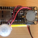
Place the ultrasonic sensor perpendicular to the slot opening. The trig transmitter and echo receiver should be (almost) flush with the opening. Use the sticky back velcro strips to affix the Arduino to the underside of the ballot box lid.
Plug the barrel jack of the battery pack (with batteries inside) into the Arduino DC jack. Use sticky back velcro strips to affix the battery pack to the underside of the ballot box lid as well. You may need to use multiple strips to hold the battery pack.
Once you’ve got a secure velcro connection, you can power the battery pack on, put the lid on the box, and start casting ballots!


