

Introduction: Ultrasonic Parking Aid


There are several instructables already that use the HC SR-04 ultrasonic distance sensor as a parking spotter; this one is mine. Points of interest to this one:
- Uses the Arduino stack, but the hardware is a custom PCB, which allows for very low-power standalone operation from two AA batteries.
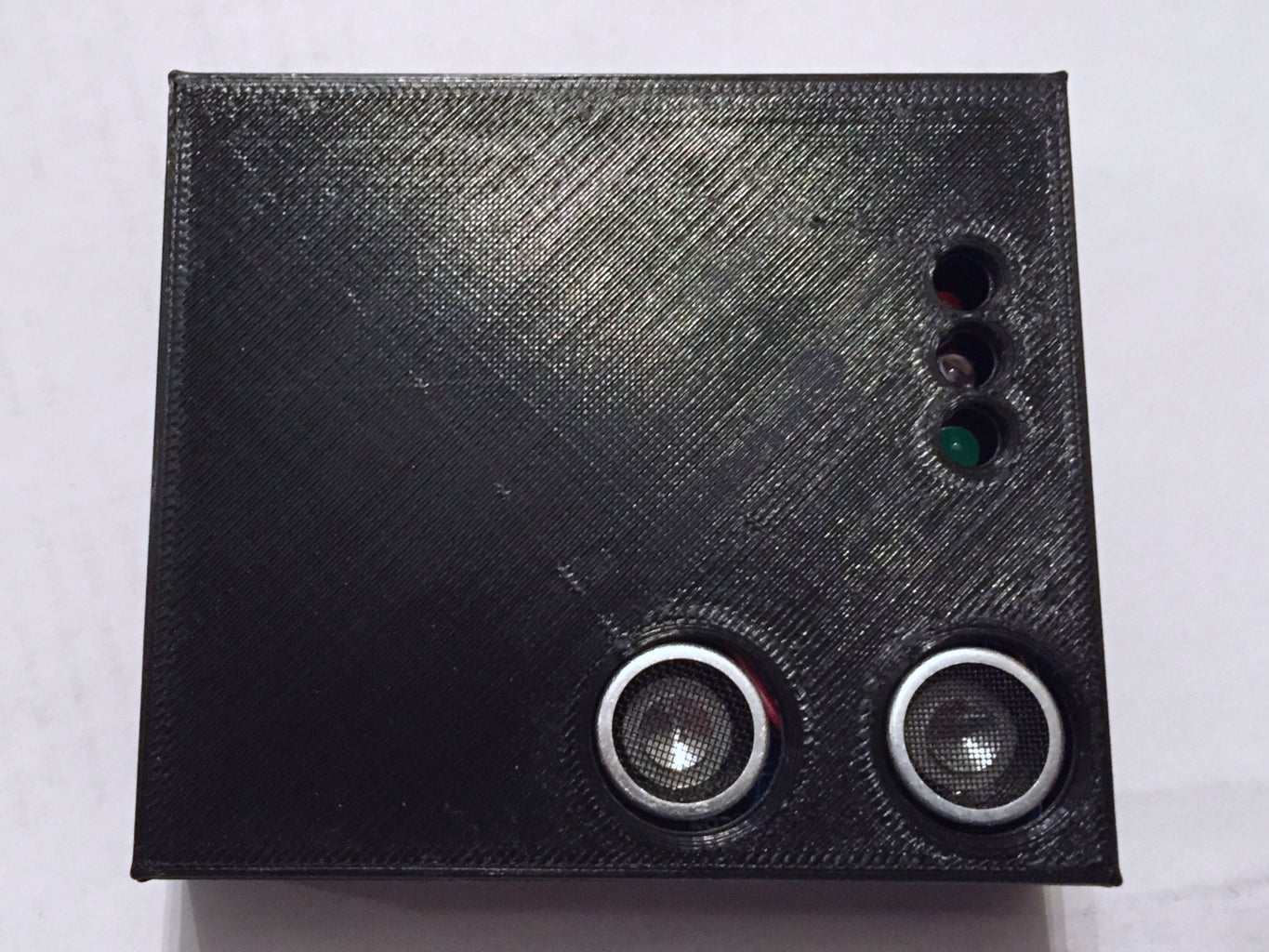
- Only three LEDs, red/yellow/green. The yellow LED blinks at a frequency corresponding to distance, which gives a good indication of how close you have to go.
- Push button for
- 3D printed enclosure.
A video of it in operation is here.
The schematic and board layout can easily be modified in Eagle to support your own low power projects by simply deleting the bottom third of the schematic and placing your own project specific components. The Arduino-related portion of the schematic is taken from the Arduino Pro Mini.
Step 1: Obtain PCB and Components
The Eagle design file for the PCB (and all project related files) are on github. You can get three boards for $9 shipped from OSH Park; delivery will take about two weeks.
The bill of materials, with Digikey part numbers:
- (1) ATMega328P (ATMEGA328P-AU-ND)
- (1) LTC3525 5V boost regulator (LTC3525ESC6-5#TRMPBFCT-ND)
- (1) 8 MHz SMD ceramic resonator (478-4584-1-ND)
- (1) 22 uF ceramic capacitor, 0805 (490-1719-1-ND)
- (1) 1 uF ceramic capacitor, 0805 (1276-1029-1-ND)
- (1) 10 uH SMD inductor (490-6614-1-ND)
- (3) 0.1 uF ceramic capacitors, 0805 (399-1170-1-ND)
- (2) 10K resistors, 0805 (311-10.0KCRCT-ND)
- (4) 180 Ohm resistors, 0805 (RMCF0805FT180RCT-ND)
- (1) BS170 n-channel MOSFET, SOT23 (BS170FCT-ND)
- (1 each) red/yellow/green 5mm LEDs (1080-1120-ND, 1080-1104-ND, 1080-1128-ND)
- (1) SPST push button momentary switch (SW400-ND)
- (1) 6 pin single inline male header (952-2270-ND)
- (1) 4 pin right angle female header (S5479-ND)
- (1) 3x2 male header (952-2120-ND)
- (1) 2AA battery holder (RadioShack 270-408)
That should total ~$14 not including shipping. You will also need an HC SR-04 ultrasonic sensor, which can be had for a couple of dollars each on eBay.
Step 2: Assemble the Board


You will need to be comfortable with soldering surface mount components. There are many tutorials on the internet, if you have not done so before. The hardest parts to solder are the boost chip and the microcontroller; look up "drag soldering" techniques. You will want some copper braid in addition to your soldering iron and solder.
The board does not have component labels on the silkscreen, so you must refer to the Eagle brd file for placement.
When placing the LEDs, ignore the "short leg" and align the flat side with the placement markings on the silk screen. I've run into LEDs with the short leg on the "wrong" side.
You can solder the battery leads directly to the board, but I recommend you use pair of male/female headers to allow easy connections, and to provide some strain relief. One of them should be right angle, to have the power leads coming out to the side rather than straight up.
(The photo above is an early prototype, missing a pullup on the sensor, the MOSFET to turn off the sensor when not ranging, and a patch wire.)
Step 3: Program the Board
You will need an ICSP programmer to program the board, and an FTDI serial breakout board. For the ICSP programming, you can make use of another Arduino, but I recommend the USBTinyISP from Adafruit. The FTDI breakout board is useful if you want to write/debug your own sketches, but can be omitted if you are just using my code.
If you wish to burn sketches without debugging straight from ICSP, you can use this boards.txt descriptor, taken mostly from the Arduino Pro Mini, which this hardware resembles:
atmega328t.name=ATMega 328 (8 MHz) - USBTinyISP
atmega328t.upload.using=arduino:usbtinyisp atmega328t.upload.maximum_size=32768 atmega328t.upload.speed=57600
atmega328t.bootloader.low_fuses=0xFF atmega328t.bootloader.high_fuses=0xDA atmega328t.bootloader.extended_fuses=0x05 atmega328t.bootloader.path=atmega atmega328t.bootloader.file=ATmegaBOOT_168_atmega328_pro_8MHz.hex atmega328t.bootloader.unlock_bits=0x3F atmega328t.bootloader.lock_bits=0x0F
atmega328t.build.mcu=atmega328p atmega328t.build.f_cpu=8000000L atmega328t.build.core=arduino atmega328t.build.variant=eightanaloginputs
If you want to program a sketch using the serial port, you must burn the bootloader using ICSP. You can then use this boards.txt descriptor with an FTDI breakout board. I recommend the one by Sparkfun; make sure it brings out DTR as the first pin to allow for auto reset.
atmega328s.name=ATMega 328 (8 MHz) - Serial
atmega328s.upload.protocol=arduino atmega328s.upload.maximum_size=30720 atmega328s.upload.speed=57600
atmega328s.bootloader.low_fuses=0xFF atmega328s.bootloader.high_fuses=0xDA atmega328s.bootloader.extended_fuses=0x05 atmega328s.bootloader.path=atmega atmega328s.bootloader.file=ATmegaBOOT_168_atmega328_pro_8MHz.hex atmega328s.bootloader.unlock_bits=0x3F atmega328s.bootloader.lock_bits=0x0F
atmega328s.build.mcu=atmega328p atmega328s.build.f_cpu=8000000L atmega328s.build.core=arduino atmega328s.build.variant=eightanaloginputs
If you wish, you can run at 16 MHz instead of 8 MHz by using a different resonator, and selecting the Arduino Pro Mini 5V 16MHz 328P board.
The sketch on github uses the NewPing and JeeLib libraries, to interface with the sensor and to enable low power sleep. I found that the SR04 draws 11 mA measured at the battery when "idle", so it needs to be shut down between ranging attempts. There is an n-channel MOSFET with a pulldown resistor and a gate current limiting resistor acting as a low-side switch, to shut off the sensor when not active. Some special consideration needs to be taken when switching the sensor; you must disconnect the trigger pin by setting it as an input, or it will find ground through it and continue to consume power. When coming back online, the echo pin stays high resulting in a short read; a sacrificial ping after a short delay seems to reset the sensor to a normal state. There is also a trace to connect the battery directly to an analog pin, to measure the battery voltage. The sketch reports out the voltage using a sequence of red and green blinks during parked mode, and will also go to a low battery mode when the voltage drops below 2V, blinking red until it dies.
The sketch currently defines the RED/YELLOW/GREEN trigger distances at 40, 150, and 500 cm. When in the yellow range, it will flash from between 20 millihertz to 1 Hz using timer interrupts, providing a visual indication of how close you are getting to red. These values can be changed by modifying the constants at the top of the file.
The sketch can easily be modified to work with a regular Arduino, but then it won't be very low power.
Step 4: Print the Enclosure


You can use the supplied STL files to print a suitable enclosure, or design your own. The photos show some previous versions of the case. The current version uses a side by side layout rather than having the battery stacked below the board. The lid snaps on using small neodymium magnets.
The board mounts to the stand offs using #4 3/8" screws; the stand offs are sized to self tap.
Step 5: Mount
You can mount the project box using double sided mounting tape. I find that the clear Scotch "Removable Mounting Squares" have enough stick, and won't damage the paint on your wall when you go to remove it. It should be mounted as low as possible while the LEDs are still clearly visible from your driving position.
I have tested out the latest revision (1.3) with the components to switch off the sensor when not active, and the power usage is unmeasurable with my multimeter when idle, so it looks like it should last a decent amount of time.

Participated in the
Battery Powered Contest

Participated in the
Home Technology Contest


