

Introduction: Upright Laser Harp


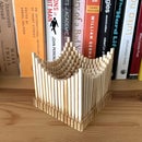

Laser harps are musical devices with laser beam "strings." When the beam is blocked, a note is played by the instrument. Usually laser harps have the beams travel vertically in the shape of a fan or vertical lines.
In this project, I built a laser harp with stacked laser beams that propagate horizontally. The beams reflect off mirrors to form square shaped beam paths. With this design, the lasers land on "frets," which makes it much simpler to block notes with a single finger. Instead of a MIDI output like my previous laser harp, this device has built-in MIDI player so the output is an audio signal. This means the device does not have to be connected to a computer or MIDI player (e.g. keyboard) to play sound. Both built-in speakers and audio output jack are available for playing music.
In this instructable, I will go over the construction and how to play the instrument.
Supplies
See below.
Step 1: Supply List


Supplies:
- Arduino Mega
- Adafruit Music Maker Shield
- 3mm thick plywood
- Black acrylic
- Clear acrylic
- 12 laser diode modules (650nm, 5mW)
- 12 photoresistors
- 12 1kOhm resistors and 12 30kOhm resistors
- 12 npn transistors
- 28BYJ-48 ULN2003 5V Stepper Motor + ULN2003 Driver Board
- Rotary encoder
- Latch pushbutton for speaker on/off
- Power switch
- 5kOhm potentiometer
- Audio jack
- Power jack and cable
- 12V Power supply - with this supply I had to solder a 5.5 x 2.5 mm cable to match the jack (this could be better planned)
- Momentary pushbutton for reset
- Hall effect sensor
- 2mm diameter magnet
- 8 ohm speakers
- 1/8" audio cable
- USB extension cable and panel mount
- Header pins
- Wire wrap wire
- Electrical tape
- Super glue
- Metric hardware
Tools:
- Laser cutter
- Soldering iron
- 3D printer
- Wire cutters
- Allen wrenches
- Small hammer
Step 2: System Overview

The upright laser harp consists of 12 lasers and photoresistors arranged in six layers. Two mirrors per layer reflect the laser beams to the photoresistors. In the figure, the red arrow indicates how the laser is reflected to the photoresistor and the corresponding pins the laser and photoresistor is connected to. The pins are scrambled up due to the way the wiring feeds down the tower to the Arduino Mega. The lasers can be triggered on and off using digital pins, and the voltage drop across the photoresistors is measured using analog input pins. When the laser is blocked, the resistance of the photoresistor increases and the voltage output drops.
The instrument produces audio output using the incredible Adafruit Music Maker shield. I was so happy to discover this shield, because I can now easily produce audio signals from the device without connecting a MIDI player. Check the link for all the info on how to set up this shield. The shield is run in MIDI mode with the audio output being run to audio jack and speakers. A latched pushbutton turns the speakers on and off. Here is a link to the chip (VS1053b) at the heart of the music maker shield. Page 33 has all the instruments.
The volume of the device is controlled using a potentiometer connected to the Arduino Mega. The output is read and software updates the volume of the MIDI signal. Finally, the device can also switch between different MIDI instruments. A rotary switch is read and the output is used to update the instrument. I chose to have 16 preloaded instrument selections on the device. The number of instruments is not limited by the Arduino and music shield. There are over 100 options for instruments on the VS1053 chip. I think there is probably enough memory on the mega to store all those instrument codes if you wanted. The selected instrument is displayed on a wheel with 16 spokes. The wheel is turned using a stepper motor, which is controlled with 4 digital pins.
Step 3: Chassis Design and Cutting


The system was designed in Fusion 360 and is constructed out of plywood and plexiglass. The methodology for designing and building the device was different from my previous projects. I focused on building subassemblies that functioned in isolation and then were added to the overall assembly. For example, the instrument wheel and kinematic laser mount took a lot of time to design and troubleshoot in isolation before adding to the completed assembly.
The parts were lasercut and assembled using alignment tabs, bolts, and super glue.
Note: The tolerances on the parts are not perfect, so you may have to trouble shoot or shave down parts so they fit.


Step 4: Mirror Assembly


The upright laser harp consists of twelve mirror assemblies and each assembly consists of five parts. Two brackets slide into the square mount and a 1" x 1" mirror snaps into place. To prevent the mirror from sliding out of the mount, two C-shaped joints slide in over the mirror. No glue is required for this assembly.
Step 5: Kinematic Laser Mount Assembly


The laser mount was the most difficult assembly to test and design. I wanted to be able to steer the laser for alignment with the photoresistors. In my previous laser harp, the lasers would get misaligned when I moved the device and there was no good way to finely adjust the lasers. Kinematic mounts are crucial components for optical systems, so I looked at existing devices for inspiration. All these devices use springs to apply adjustable force at specific locations in the device. My goal was to build low-cost kinematic mounts, which meant replacing the metal springs with other materials. In my search, I also came across these LEGO-based kinematic mounts.
My first designs placed the mirrors on kinematic mounts with rubberbands. This worked pretty well, but the mounts were bulky and difficult to put together. I started to think of ways to make wood spring-like so I could avoid the springs and rubber bands. The final design consists of wooden arms with slits in them that made them flexible.
The mount consists of nine parts. First the rear body is put together with glue and four nuts placed inside. This part holds the screws that push the part holding the laser. Two parts holding the laser are glued together with the holes facing the screw. Finally, the three "spring" arms connect the front part and the part holding the laser. The laser is placed into the device later.
The process for holding the entire assembly together is described in the next step.
Step 6: Photodetector Mount


To detect the blocked laser beam, I decided to use photoresistors. I debated using faster components, but after watching this great Backyard Amusement video, I realized that photoresistors would work fine given my requirements.
Even with the kinematic laser mounts, I knew that I wanted to add diffusers to make sure light fully illuminated the photoresistors. I used old 35mm film canisters cut to fit in a small mount, a trick I learned from my first laser harp.
A photoresistor is pushed into the photoresistor "wall," and two cables are connected to the photoresistor (one goes to 5V and the other goes to an analog input). I then cut a small piece of diffusive plastic from a camera film canister. The plastic then slides into wooden mounts and is placed into a cross-shaped part. It looks like a little lantern. The body is pressed into the photoresistor wall. Finally, the photoresistor wall is used to connect the kinematic laser mount assembly.
Step 7: Top Assembly (Layers 1-2)


The top two sheets of the laser harp don’t hold any lasers. First, the corner brackets are pressed into Layer 2. The orientation of the brackets matters because of how they fit into Layer 3 in the harp. Layer 1 is then pressed into the top of the brackets. Four square pieces of wood are glued onto the top of Layer 1. This assembly is set aside before attaching to Layer 3.
Step 8: Laser Layer Assembly (Layers 3-9)


These layers hold together the laser, photoresistor walls, and mirror assemblies. All the layers are the same except for layer 3, which has additional holes for mounting the top assembly. For each row, the laser/photoresistor and mirror positions alternate, as shown in the schematic. I pressed in the laser/photoresistor modules and mirrors into the layers using a hammer. Some of the tolerances were off, so I had to shave down the tabs on the mounts so they fit into each layer.
At each layer, the lasers and photoresistor wires are threaded down through holes to the next layer. The ground of each laser is connected and the 5V from the photoresistors are connected together. I also labeled the wires so I knew how to connect them in the electronics box at the bottom of the device.
When all the laser, photoresistor walls, and mirror assemblies are mounted into the layers, long arm connectors slide into the layers to hold everything together.
Step 9: Base Assembly (Layers 10-15)


The next step is to start assembling the base. Layers 10-15 were designed to form a converging tunnel in the middle of the device when seen from the top. I pressed the two sides of the electronics box into these layers to hold them in place. Layer 14 and 15 are glued together and Layer 14 has no tabs to be be pressed into the walls of the electronics box. The front and rear wall of the electronics box are not initially pressed into the layers.
The wires from the lasers and photoresistors are then pulled through the holes in the base assembly so they can eventually be connected to the Arduino. Layers 3-9 are connected to the base assembly with tabs on Layer 9 that fit into the walls of the electronics box.
Layers 1-2 can now be pushed into holes on Layer 3. Finally, even longer connector arms are pressed into Layers 1-15 to hold all the layers together and connect the top portion of the instrument to the electronics box.
Step 10: Wheel Assembly


The stepper motor is secured onto the mount with two bolts. There is directionality to this mount; see the CAD model gif and video to make sure everything is in the right direction. A 3D-printed motor coupler connects the motor shaft and wheel axle. The two axle pieces are glued together and pushed into the coupler. Then the first face of the wheel (the one with the bigger rectangular cutout) slides over the axle, followed by the second face of the wheel. Some wax may be required because it is a tight fit. The rim of the wheel with the instrument types holds the two faces together. The words will be upside down when viewing the wheel with the first face to the right of the second face.
Next the two parts holding the Hall effect sensor are glued together. The Hall effect sensor is used to determine the position of the wheel. The bipolar Hall effect sensor switches high to low when the magnet field over the sensor changes. Two magnets are therefore placed on the wheel facing opposite directions. The wheel rotates until the sensor reads high and then switches to low. Some offset in steps is then added to position the first instrument at the right position in the display.
The Hall effect sensor is pushed into place with housing over the middle lead to avoid a short. Check the wiring in the schematic. Now three circular parts slide over the axle so that the axle can turn in the circular hole in the Hall effect sensor mount. Two C-shaped parts are pushed orthogonally into the axle to hold everything in place.
The motor is then connected to the axle via the coupler, which holds a nut and set screw that presses into the motor shaft. Finally, the whole assembly is held together with two spline shaped mounts.
Step 11: Box Component Mounting


I designed all the electronics to be mounted to the top of the electronics box so that the bottom panel could easily be removed if the electronics needed to be troubleshooted. The Arduino Mega, stepper motor controller, prototype board, and instrument wheel are all pressed into the top of the box using the mounts.
A few lasercut parts slide over the boards as shown in the images above. These parts then press into the holes in the top of the box. All the electrical components shown in the diagram are soldered to the prototype board: transistors for controlling the laser diode modules, resistors for the photoresistor circuit, pins for front panel components. There is a lot of soldering work here so I'd like to some day make a PCB for the upright laser harp.
Make sure to wire the Adafruit Music Maker according to the MIDI configuration in the instructions on Adafruit's website.
Step 12: Front and Rear Panel


I decided to build the device with two separate panels. In the rear are the jacks and switches for power and uploading programs to the device. In the front are all the controls related to controlling the instrument and audio of the device.
Black acrylic pieces hold the components on the rear and front panel. Both acrylic panels are glued onto the wooden front and rear walls of the electronics box. After gluing the acrylic, I mounted the potentiometer, rotary encoder, on/off speaker switch, and headphone jack. On the rear, I attached a reset pushbutton, on/off power switch, power jack, and USB jack for uploading programs to the Arduino.
The front and rear walls were then hammered into Layers 10-15, just like the side panels. At this point, I also connected the corner joints at the bottom of the device. A nut is glued into these joints so that bolts can hold on the bottom panel.
I did a lot of soldering and wire wrapping to connect all the components as shown in the schematic. The power supply is 12V, so I made sure the Buck converter was adjusted for 4.5V output before connecting lasers and the motor. Finally outer walls for the electronics box were glued on to cover the Layer 10-15 tabs.
Step 13: Playing the Harp


Attached is the code for the laser harp and some additional troubleshooting code. I followed the code from the Adafruit documentation for the Music Maker shield. The general procedure is as follows:
SETUP
1. Calibrate the instrument wheel with Hall effect sensor signals
2. Set up Music Maker Shield for MIDI output
3. Select the notes played by the device
4. Turn lasers on
LOOP
5. Update volume of device by reading the potentiometer
6. Update the motor position and MIDI instrument by reading rotary encoder
7. Read the state of the photoresistors and compare to previous state to determine if beam was blocked
8. Send appropriate MIDI signal if beam is blocked
The Reset button and Speaker enable button work by being tied to ground so they don’t have to be read into digitial pins of Arduino. You may have to adjust the lasers using the kinematic mounts to make sure they are aligned with the photoresistors.
Now you are ready to play the instrument! The device plays like a fretted instrument because of the rails running down the sides of the device, so it is easier to play than other laser harps I have tried. Thanks for reading my instructable!


