

Introduction: Use Your Camera to Capture "3D" Anaglyphs

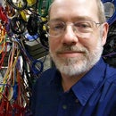


An anaglyph is a color image that creates the illusion of "3D" depth when viewed through color filters that separate the left and right views. The image shown here is an example viewable through green/magenta glasses.
Although various color combinations and processing variations have emerged over the years, the basic concept of an anaglyph is largely unchanged since the 1850s. Nearly all methods start by capture of a stereo pair of images which are then manipulated to create the anaglyph. In contrast, the method discussed here involves modifying a digital still or video camera to directly capture a high-quality anaglyph in a single shot -- with no post-processing needed.
Did I mention that the reversible modification to your camera can cost less than $1?
Step 1: What You Need

The parts you'll need are:
1. The camera and lens to be modified
2. Two pairs of identical paper anaglyph viewing glasses
3. A method of mounting (paper, tape, and scissors; optionally, a lenscap and drill)
This method works with most cameras and lenses, but works much better with some than with others and is a little touchy about some details. Don't be scared by the large number of steps in this instructable -- that's just trying to make sure that you get things working as well as possible without a trial-and-error process. This is easy.
Cost? Well, you probably have most of the stuff you need. The paper anaglyph viewing glasses are widely available for free in small quantities. I've bought hundreds at an average cost of $0.32 each including shipping, which would bring the "new purchase" cost to $0.64 for the two needed... easily under $1. Using a lenscap instead of paper printout for mounting adds about $1 to the cost, but yields a "more professional looking" and more durable device.
Note that the post processing described in steps 12, 13, and 14 is optional. You don't need a computer to make anaglyphs by the method described here.
Step 2: Theory
Ok, I know you don't want to hear about the theory behind this, but I'm a professor, so you're going to. Beyond that, although the method is quite simple, there are details that can make a huge difference in how effective the method is.
The key is understanding what happens to the out-of-focus (OOF) portion of an image. An image is nothing more than the sum of what the lens does to each point of light in the scene. Most people, including many otherwise really smart people writing fancy image-processing algorithms, think that an OOF image of a point of light looks like a Gaussian blur -- but that's not how lenses work. For a typical well-corrected lens, the image of an OOF point light source is actually a bright disc whose sharp outline is shaped like the lens aperture. In fact, there are a couple of instructables that take advantage of this fact to make OOF points take-on interesting shapes, giving lenses very distinctive bokeh.
Technically, the shaping is caused by hard-clipping of the point spread function (PSF) of the lens by the aperture. That implies the light near the edge of the OOF point's image actually came through the lens near the corresponding edge of the aperture. Since opposing edges of the aperture have a distance between them, all we need to do is distinguish rays coming through near the leftmost and rightmost edges -- we can capture a stereo pair in a single shot with a single lens! A larger distance between the edges allows a greater interocular distance and a more extreme stereo effect.
I've been working on methods that can computationally perform this separation for well over a year... it's a very hard problem. However, it isn't hard to separate the two views by imposing a special, color-coded, aperture. An appropriately-coded aperture can directly produce the stereo pair encoded as an anaglyph.
In fact, J. D. Songer's 1973 patent, #3,712,199, teaches coloring of the halves of an aperture to capture anaglyphs. The discontinued and rare Vivitar Series 1 Qdos 70-210mm lens even implemented this trick using a special segmented internal filter. The method described in this instructable is conceptually very similar, but is much simpler and cheaper to implement -- and it captures higher-quality anaglyphs.
Step 3: Determine the Mount Diameter for the Stop

You are going to make an aperture stop that will be placed in front of your lens, not unlike the stops other instructables have suggested for bokeh shaping. However, precision matters more here, so we're going to go through the technical steps to maximize the probability that it works for you.
Fisheye and other ultra-wide-angle lenses often have bulbous front elements that don't provide a simple front-mounting option for a new stop. You can't use one of them unless you put the stop elsewhere, and that's beyond the scope of this instructable. Sorry.
For many lenses, there is a thread for screw-in filters. If your lens has that, note the filter thread diameter marked. Relax; mounting will be neat and easy.
If your lens doesn't have a thread (most compact camera lenses don't), use a ruler to measure the diameter of the rim around the lens. Be careful to measure only the portion that moves with the front glass element for an extending lens, not the diameter of the whole assembly. We will treat this number as your filter thread diameter, although mounting will be less elegant, perhaps using a little sticky tape.
Step 4: Determine the Best Minimum F/number for Your Lens

Although this method will work with most lenses, it works much better for some lenses than for others. Lenses that allow a larger stop are easier to use and can produce more dramatic stereo by having a wider stereobaseline or interaxial distance .
You'd think the lens with the widest front element would work best, but that is not quite true. Severe artificial vignetting will degrade anaglyph quality by introducing both color casts and stereo depth errors. Thus, we need to determine the widest aperture at which this vignetting is kept to an acceptable level.
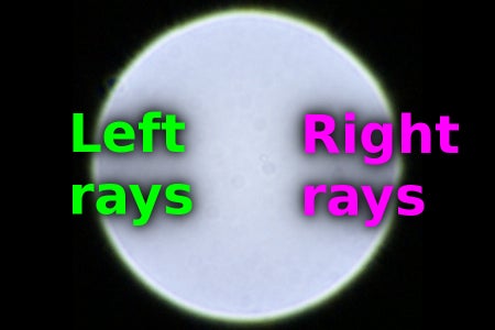
Artificial vignetting generally causes the PSF shape to change (be clipped) as you move away from the center. If you have a removable lens, you can see this effect by taking the lens off your camera and looking through it at an angle similar to what's needed to reach the image edge (see photo). A more precise method is to hold an LED flashlight in front of your camera and observe how it's OOF PSF image changes as you move the light from image center to image corner. Start with the lens wide open and stop it down (increase the f/number) until the shape distortion is minor.
Often, wide open is ok. However, especially for very fast lenses, it is common that stopping down a little will significantly reduce this type of vignetting. A few lenses, especially on compact cameras, have severe artificial vignetting at all usably large apertures; they will never work well with the method in this instructable.
The smallest f/number (widest aperture) at which the shape distortion is acceptable is the f/number you should use. I like to see no more than a 25% PSF size reduction due to clipping near the image corners.
If you have a zoom lens, repeat this procedure for several focal length settings. The combination for which the focal length divided by the f/number is largest probably will work best, but you could make stops for each combination.
Step 5: Design the Stop
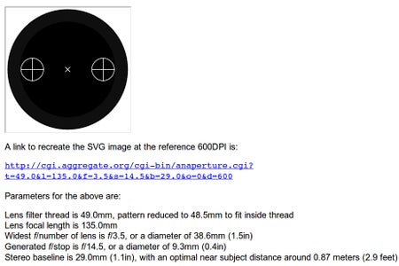
You now have the basic data needed to design the stop. That's slightly tricky, so we've built a free tool to help you: http://aggregate.org/anaperture . Scroll down and fill out that WWW form as follows:
Lens filter thread is marked : your value from step 3
Lens focal length is:true focal length of your lens
Widest f/number of lens is f/:your value from step 4
Desired f/stop is f/:0 to automatically select
Desired stereo baseline is:0 to automatically select
Click on the "Design Aperture Stop To Parameters " button. In a few moments, you'll get a page with an SVG image of a stop designed for your lens. The anaperture tool tries to maximize the image brightness, so the generated stop will have the smallest possible f/number, but you can re-run the tool to investigate different design options.
Alternatively, instead of making a template for a paper/cardboard aperture, there is now a version of anaperture to make 3D-printable versions. It is available as a customizer script at https://www.thingiverse.com/thing:1574072
Step 6: Print the Stop

You could just use the measurements from the anaperture design to make your own stop without printing it... but printing is easier and usually more accurate.
Print out the SVG design on paper or thin cardboard using the DPI listed. Linux systems often ignore the SVG DPI setting, but you can load it into GIMP, set the DPI for the image, and print it from there (see screen shot).
If the paper is too thin, this is also a good time to use a black marker to darken the unprinted back of the stop design. Also, reinforcing shouldn't be necessary, but you can tape over the unprinted side of the stop design at this time to help reinforce it.
Step 7: Cut Out the Stop and Apertures

Cut out the disc. You now have two options:
1. Using the disc as a template, drill the aperture holes into a lenscap.
2. Cut out the apertures. Using scissors, this is easiest if you temporarily fold the disc along the center line through the two apertures and then cut the folded piece. For the truly tiny apertures that are commonly needed with compact cameras, it is easier to use a pin or needle to make the holes.
If you have access to a stencil or laser cutter, that is the most precise way to do this!
In any case, you now have a stop with left and right apertures.
Step 8: Get Color Filters

There are many places you can get color filters to use for making anaglyphs.
If you want to experiment, the Roscolux Gel Sample Swatchbook contains many calibrated theatrical lighting 1.75x2.75" gels and sells for about $2. However, we really want the viewing and capture filters to match, so cutting-up an extra pair of cardboard viewing glasses to get the filters works nicely.
Anaglyph viewing glasses come in many color combinations, but all color combinations are not equally effective for anaglyph capture. The primary reason is that most digital camera sensors distinguish colors using a Bayer filter with a repeating pattern containing two greens, one red, and one blue. Thus, in order to minimize ghosting and balance capture resolution between the left and right views, we are forced to code one side as green and the other as magenta (red plus blue). It doesn't matter much which side is which, but green-left glasses are most common.
Red/cyan glasses would be the obvious second choice among the commonly-available viewing colors. Of course, you have to use the same color combination for both capture and viewing (unless you do some fairly scary post-processing).
These are all gel filters that scratch easily, so avoid handling them.
Step 9: Mounting

It is very easy to mount the colored filters to cover the aperture holes. Simply cut them slightly oversize and use a tiny piece of tape on the edge to hold it in place. It works slightly better if the dark side of the stop is facing the lens and the filters are taped to that side.
If you are modifying a lenscap, simply affix the cap normally.
If you are using the printed design template with a threaded filter mount, take a piece of tape and fold it back on itself to make a tab on the side of the stop facing away from the lens. The stop should be able to be simply pushed into the filter thread. The tab is needed because the threads really do hold the stop firmly in place.
If you are using the printed design template with a compact camera that has no threaded filter mount, the best solution is probably to tape the stop to the lens surround.
Step 10: Basic Capture of Anaglyphs

Ok, you're ready to put the stop on your camera and capture some anaglyphs. Make sure you put the stop on straight with the colors on the same sides as in the glasses. One of the nice things about this method is that it is easy to rotate the stop so you can capture your images in either landscape or portrait orientation. Your camera will handle a bit differently now, but not too differently.
You need to ensure that your camera doesn't set the aperture iris within the lens smaller (larger f/number) than you determined in step 4. If it does, the stop in front of the lens will not function as the effective aperture, but as a vignetting element.
Your new stop also will significantly reduce the light coming through the lens. At most, the two apertures each approach half the diameter of the original aperture of the lens. Half the diameter is 1/4 the light transmission. You might think that having two doubles the light, but the color filters approximately let each color pass through only one of the two apertures, so they together let in the same amount of light as one unfiltered aperture. Less light means longer exposures and a darker optical viewfinder if you are using an SLR; composition of images is much easier using an electronic live view that "gains up" appropriately.
Although anaglyphs are very sensitive to color shifts, your camera's white balance setting probably will be fine on auto. The two color filters are intended to partition the spectrum, so together they should come close to having no color bias at all. The auto white balance may correct small color casts at the expense of a slight increase in ghosting due to subtle differences between the anaglyph filters and camera's color space. Post-processing with "auto levels" and/or color-correction transforms will have much the same effect.
Step 11: Anaglyph Focus and Framing

Although you can capture anaglyphs that will show good stereo separation without paying much attention to focus, focus doesn't just determine what is sharpest in anaglyph capture, but also how far away each object appears to be.
Phase-detect autofocus systems will not function while the color-coded stop is in place and contrast-detect autofocus is mildly impaired. Either autofocus with the stop temporarily removed or manual focus will usually work best. Use the absence of color fringing to judge manual focus point -- the whole screen becomes a double-image rangefinder!
The tricky part is that the small apertures in your stop should give a relatively large depth of field -- objects within a larger range of distances will be acceptably sharp. However, the colors will only align at the point you focused on.
In anaglyph imaging, creative separation of the point of sharpest focus from the point of color alignment is a big deal. Where the colors align will appear to be at the front surface of the display or print when viewing. Things in front of that point appear to jump out of the frame at you, which is very disturbing if those objects get clipped by the edge of the image.
Thus, if you will not be post processing to separate the focus point from the color registration point, it is probably best to focus on the nearest object in the scene, or at least to frame the image so that closer objects do not intersect the edge of the frame. On some of the larger and better live view displays, you can effectively compose your shot in 3D if you wear anaglyph glasses, thus making it much easier to avoid bad object depth placement issues.
Step 12: Post Processing to Adjust Depths
Aside from the usual 2D image editing, the most likely post-processing you'll want to perform involves adjusting the apparent depth of objects relative to the display or print surface.
As mentioned in step 11, as captured, the object(s) you focus on will appear to be at the surface of the display with closer things popping out. Although many 3D movies have deliberately placed objects far in front of the surface to give in-your-face impact, it really isn't a pleasant or natural way to see most scenes. Thus, it often is better to adjust the encoding so that the display behaves like a window, with 3D features all "behind the glass."
If you plan on post-processing to push objects behind the surface, you don't need to focus on the nearest object. Instead, you can use focus to isolate a particular object just as you would in 2D photography.
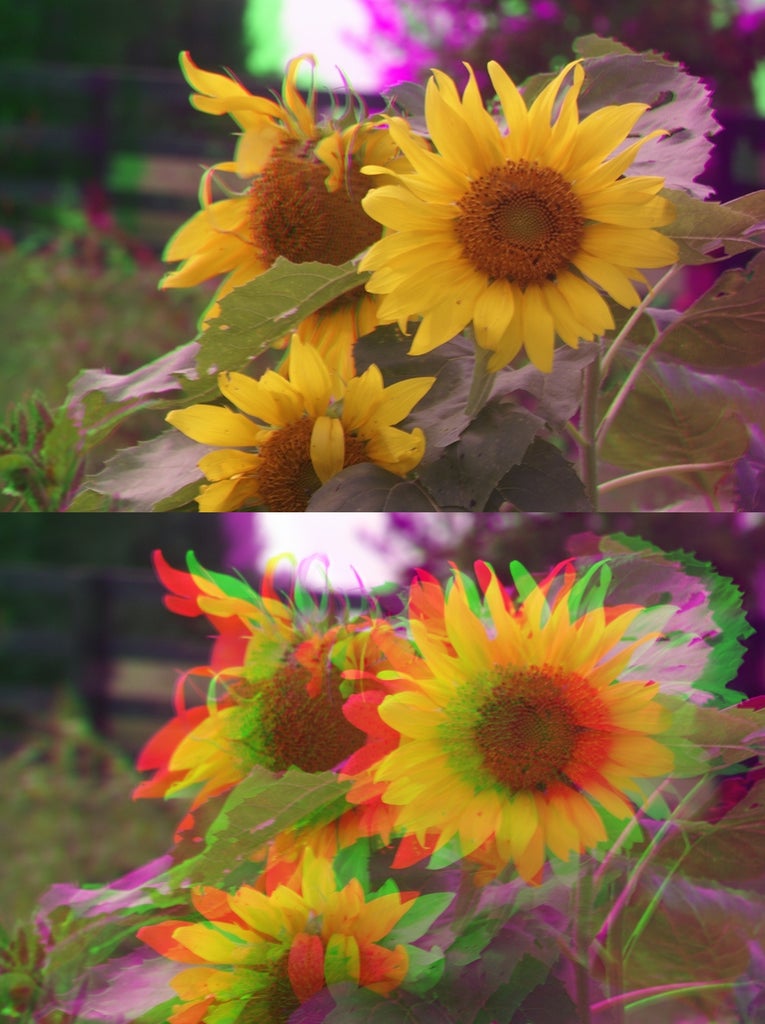
The post-processing to change what is at the surface is quite simple. For example, using GIMP with a green/magenta anaglyph, simply use the Decompose tool under the Colors/Components menu. Decompose the image into red, green, and blue layers. Slide the green layer left or right so that the object you want to be at the surface lines-up between the green and red/blue layers. If the shift is significant, you may need to crop the image so that the edges have full color data. Simply Compose the image when you're done.
Step 13: Post Processing to Remove Chromatic Aberrations

Lateral chromatic aberration (CA) is the lens defect that causes color fringing toward the edges of a conventionally captured image. Obviously, a lens that displaces one color relative to another will cause distortion of apparent depth in a captured anaglyph.
Using GIMP, the Chromatic Aberration filter can independently rescale the different color channels to correct this problem quite well for most lenses. Determine the correct settings to minimize CA for your lens using a non-anaglyph image, then apply that same correction to all your anaglyphs.
Step 14: Post Processing to Remove Color Tinting Due to Vignetting

The artificial vignetting discussed in step 4 causes darkening and color tinting at the image edges. Any vignetting that remains will cause the left and right image edges to be colored with a bias toward the filter color on that side. For most scenes, quite a lot of vignetting can occur without an objectionable color cast; evenly-lit backgrounds make the edge casts much more visible. This can be corrected by creating a color-correction mask.
The color-correction mask is created by shooting a featureless white surface or grey card. Using a long exposure time and continuously moving the camera during the exposure will help even-out the image. Both the color tinting and darkening caused by vignetting will be captured in this reference image. If you are shooting in a linear raw format, the correction is essentially dividing by the reference image; the gamma used in JPEG images creates an exponential space, so divide becomes subtract.
This processing unfortunately does not correct the depth error caused by vignetting. A simple alternative that eliminates both the color cast and depth error is to crop the image to the center portion that does not have a color cast.
Step 15: Parting Words

A few parting notes:
1. The most natural stereo depth perception is at about 30X the baseline distance. For most lenses using this technique, that means head shots or macros. Shots at greater distances will show very subtle depth cues... and also be viewable as 2D images.
2. Highly saturated colors that are only passed on one side of the anaglyph will be hard to visually fuse, flipping between color and black when viewed. Although it is possible to partially correct this with fancy post processing, scenes that avoid such colors will look best.
3. 2D text added to an anaglyph will appear at the display surface. This makes a very nice way to label images without synthesizing anaglyph shading of text.
4. High-quality conversion of anaglyphs in one color set to other 3D representations, including other anaglyph color sets, is a research topic, not an established technology.
Now that you know what you're doing, go take 3D pictures!
Participated in the
Epilog Challenge


