

Introduction: Use a DIY Proximity Sensor to Automate Your Haunted House


The special effects in a haunted house need to be well timed. The best way to do this is to use sensors to detect where your guests are in the haunted house. So I am doing a series of projects that demonstrate a variety of sensors that you can use to automate your haunted house. Last week I showed how to make a simple DIY pressure plate switch.
This week, I am going to show you how to make a proximity sensor and how you can implement it to activate special effects.
Step 1: Materials

Here are the materials and tools that you will need to make a simple proximity sensor:
Materials
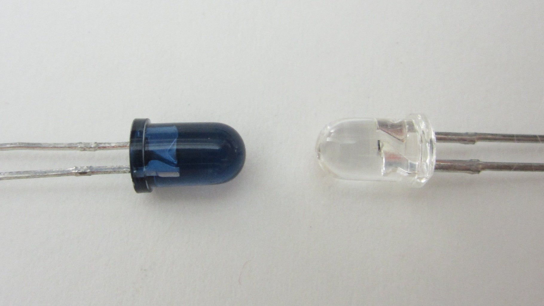
Infrared LED
Infrared Phototransistor
33 ohm Resistor
10 kohm Resistor
Black Heat Shrink Tubing (the same diameter as the phototransistor)
Perf Board
Tools:
Soldering Iron
Step 2: How an Infrared Proximity Sensor Works


To make a simple proximity sensor, all you need is a light emitter and a light detector. The light emitter is constantly on. Whenever that light hits a nearby object, some of the light is reflected back to the detector. The closer the object is, the more light will be reflected. By measuring the output of the light detector, you can get a rough approximation of how close the object it.
This isn't exact because the amount of reflected light also depends on the physical properties of the reflecting surface (sometimes called its reflectivity). However, it works well enough to use to activate special effects in a haunted house.
I chose to use infrared light for this sensor because it is invisible to the human eye. So your guests won't notice it. Also it won't experience as much interference from the lighting in the room.
Step 3: The Sensor
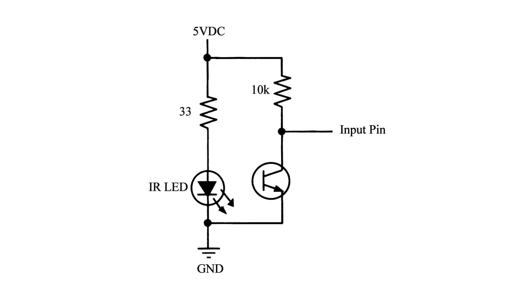

The IR LED is connected to the 5V supply with a 33 ohm series resistor. To find the appropriate resistor value for the LED use this formula:
Resistor Value = (Supply Voltage - LED Voltage) / LED Current.
In my circuit, the supply voltage is 5V. The LED is rated for 1.3V at 150 mA. This gave a resistor value of 24.7 ohm. The closest resistor that I had above this value was a 33 ohm resistor. So I used that. Be careful to not overload the resistor. A 33 ohm resistor will experience about 1/2 watt if power. If you don't have a resistor rated for that much. You can use two 68 ohm resistors in parallel. Or you can use multiple LEDs in series to bring down the voltage across the resistor.
The emitter of the phototransistor is connected to ground. The collector is wired to a 10 kohm resistor that is connected to 5V. An additional wire is connected to the collector to act as an output pin for the sensor. I soldered the sensor components together on a small piece of perf board. I added three pins to connect the sensor to the signal processor.
To ensure that only reflected light is detected by the phototransistor, it is important to add a light barrier between the LED and the phototransistor. The most effective way to do this is to put a black piece of heat shrink tubing around the phototransistor. This also helps to make the sensor more directional.
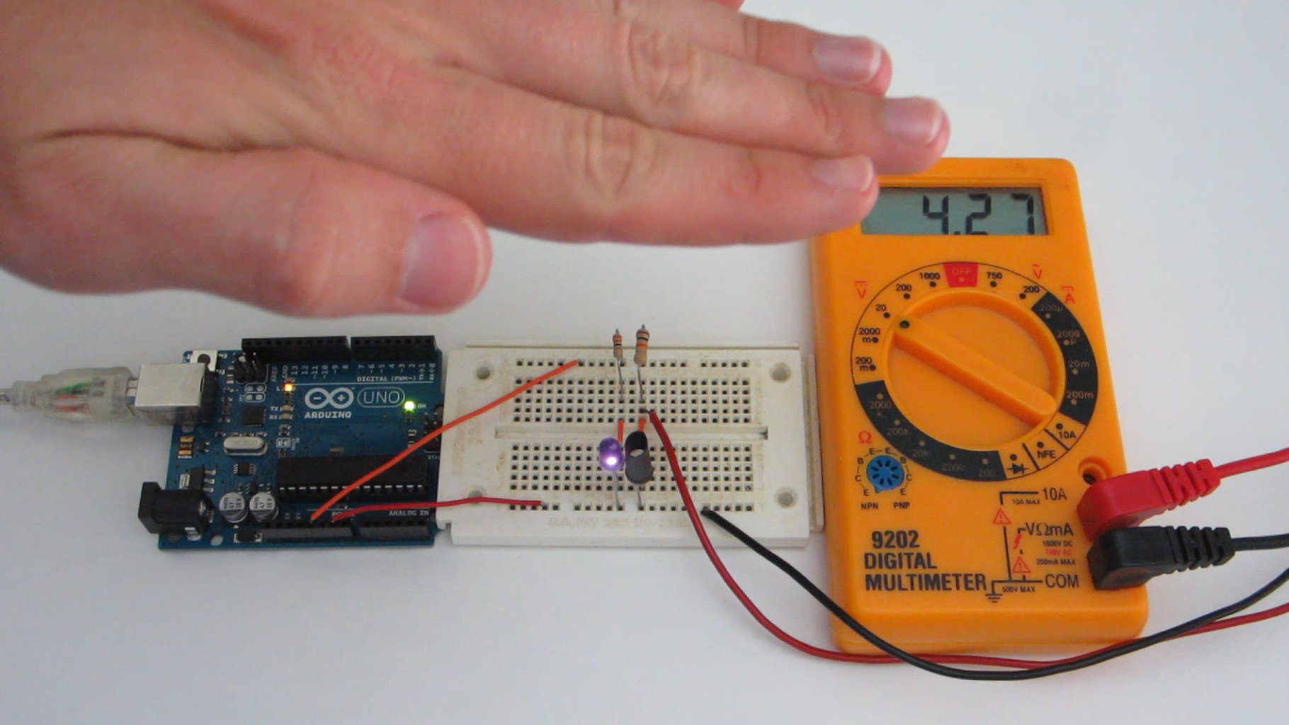
Step 4: Signal Processing With an Arduino


In most cases you will use a microcontroller such as an Arduino to monitor the signal from the sensor. To do this, connect the ground terminal from the sensor to the GND pin on the Arduino. Connect the 5V wire from the sensor to either the 5V pin or a digital output pin set to HIGH. Then connect the signal wire from the sensor to an analog input pin on the Arduino.
The AnalogRead function measures the voltage of the signal coming from the sensor. When the voltage drops below a set threshold, the Arduino activates the your special effects. Here is an quick example of the code that you could use.
// Example Code
int InputPin = 0; // analog pin 0 is the input pin
int OutputPin = 1; // digital pin 1 is the output pin
int val = 0; // variable to store the value read
void setup()
{
pinMode(OutputPin, OUTPUT); // sets the digital pin as output
}
void loop()
{
digitalWrite(OutputPin, LOW); // sets the output pin initially to LOW
val = analogRead(InputPin); // read the input pin 0 to 1023
if (val < 800) // if sensor value is below threshold set output HIGH
{
digitalWrite(OutputPin, HIGH); // sets output pin HIGH to activate special effects
delay(1000); // waits for a second
}
}
Step 5: Signal Processing With an OP Amp


If you don't have an Arduino, you can use an op-amp (operational amplifier) to monitor the signal from the proximity sensor. All you need is a 741 op-amp IC and a potentiometer (variable resistor). Connect the 5V supply to one side of the potentiometer and to V+ pin on the IC. Connect the ground wire to the other side of the potentiometer and to the V- pin on the IC. Then connect the non-inverting input (marked as "+" to the center lead of the potentiometer. Lastly connect the inverting input (marked as "-") to the signal wire from the sensor.
This configuration of the op-amp functions as an adjustable comparator. The potentiometer sets the reference voltage for the sensor. Then whenever the signal from the sensor drops below this reference voltage the output goes HIGH.
Depending on what kind of circuit you want to activate, you may want the output to be a LOW signal instead. You can do this by switching the wires connected to the op-amp's input pins. So if you connect the sensor to the non-inverting input and connect the potentiometer to the inverting input, the output will be LOW whenever the sensor is activated.
Step 6: Use Your Proximity Sensor to Activate Your Special Effects


You can use the output of this device to activate just about any kind of special effect. You can use the proximity sensor to activate a prop on a servo like my motion tracking skull project. You can use it to activate sound effects like a scream. But my favorite application is the automatic coffin. The coffin is closed as you approach it. But as soon as you get close to it, the door swings open with a zombie inside.
To see a really good tutorial on how to make an automatic coffin, check out this instructable by instructable user wannabemadsci.
https://www.instructables.com/id/Halloween-Remote-Controlled-Casket/

Finalist in the
Microcontroller Contest


