

Introduction: Using Analog Sensors With ESP8266


An analog-to-digital converter (ADC, A/D, A–D, or A-to-D) is a system that transforms an analog signal into a digital signal. A/D converters translate analog electrical signals for data processing purposes. With products matching performance, power, cost, and sizeneed. These data converters facilitate precise and strong conversion performance in a range of applications such as communications, energy, healthcare, instrumentation and measurement, motor and power control, industrial automation, and aerospace/defense. A variety of A/D converter devices is provided to help the engineer in every project phase, from product selection to circuit design.
Today, we will be using an analog-to-digital converter with an ESP8266. Let's start.. !!
Step 1: Equipments We Need


The MCP3425 is a 1-Channel Analog to Digital Converter with 16-Bit resolution, ideally suited for low-speed high-resolution sensor monitoring. The MCP3425 is capable of reading analog voltages at 15 samples per second with 16-Bit resolution or 240 samples per second at 12-bit resolution.
2. Adafruit Huzzah ESP8266
The ESP8266 is an incredible platform for IoT application development. The ESP8266 processor from Espressif is an 80 MHz microcontroller with a full WiFi front-end and TCP/IP stack with DNS support as well. The ESP8266 provides a mature platform for monitoring and control applications using the Arduino Wire Language and the Arduino IDE.
This ESP8266 host adapter was created specifically by Contol Everything for the Adafruit Huzzah version of the ESP8266, allowing I²C communication connections.
Contol Everything also designed the I²C connection cable which is available at the above link.
5. Mini USB Cable
The mini USB cable Power supply is an ideal choice for powering the Adafruit Huzzah ESP8266.
Step 2: Hardware Connections


In general, making connections is the easiest part of this project. Follow the instructions and images, and you should have no problems.
First of all, take the Adafruit Huzzah ESP8266 and place it on the USB Programmer (with Inward Facing I²C Port). Press the ESP8266 gently into the USB Programmer and we are done with this step (See picture #1).
Take an I²C Cable and connect it to the Input port of the Sensor. For proper operation of this cable, please remember I²C Output ALWAYS connects to the I²C Input. Now, connect the other end of the same I²C Cable to the USB Programmer with Adafruit Huzzah ESP8266 mounted over it (See picture #2).
Note: The brown wire should always follow the Ground (GND) connection between the output of one device and the input of another device.
Plug in the Mini USB cable into the power jack of Adafruit Huzzah ESP8266. The final connection will look like in picture #3.
Step 3: Code
The ESP Code for the Adafruit Huzzah ESP8266 and MCP3425 ADC Converter is available on our GitHub repository.
Before going on to the code, make sure you read the instructions given in the Readme file and setup your Adafruit Huzzah ESP8266 accordingly. It will take just 5 minutes to set up the ESP.
For your convenience, you can copy the working ESP code for this sensor from here also:
// Distributed with a free-will license.
// Use it any way you want, profit or free, provided it fits in the licenses of its associated works. // MCP3425 // This code is designed to work with the MCP3425_I2CADC I2C Mini Module available from ControlEverything.com. // https://www.controleverything.com/content/Analog-Digital-Converters?sku=MCP3425_I2CADC#tabs-0-product_tabset-2#include <ESP8266WiFi.h> #include <WiFiClient.h> #include <ESP8266WebServer.h> #include <Wire.h>
// MCP3425 I2C address is 0x68(104) #define Addr 0x68
const char* ssid = "your ssid network"; const char* password = "your password"; float pressure, cTemp, fTemp;
ESP8266WebServer server(80);
void handleroot() { unsigned int data[2];
// Start I2C Transmission Wire.beginTransmission(Addr); // Send configuration command // Continuous conversion mode, 12-bit resolution Wire.write(0x10); // Stop I2C Transmission Wire.endTransmission(); delay(300);
// Start I2C Transmission Wire.beginTransmission(Addr); // Select data register Wire.write(0x00); // Stop I2C Transmission Wire.endTransmission();
// Request 2 bytes of data Wire.requestFrom(Addr, 2);
// Read 2 bytes of data // raw_adc msb, raw_adc lsb if (Wire.available() == 2) { data[0] = Wire.read(); data[1] = Wire.read(); }
// Convert the data to 12-bits int raw_adc = (data[0] & 0x0F) * 256 + data[1]; if (raw_adc > 2047) { raw_adc -= 4096; }
// Output data to serial monitor Serial.print("Digital Value of Analog Input : "); Serial.println(raw_adc); delay(500);
// Output data to web server server.sendContent ("<html><head><meta http-equiv='refresh' content='3'</meta>" "<h1 style=text-align:center;font-size:300%;color:blue;font-family:britannic bold;>CONTROL EVERYTHING</h1>" "<h3 style=text-align:center;font-family:courier new;><a href=http://www.controleverything.com/ target=_blank>www.controleverything.com</a></h3><hr>" "<h2 style=text-align:center;font-family:tahoma;><a href=https://www.controleverything.com/content/Analog-Digital-Converters?sku=MCP3425_I2CADC#tabs-0-product_tabset-2 \n" "target=_blank>MCP3425 Sensor I2C Mini Module</a></h2>"); server.sendContent ("<h3 style=text-align:center;font-family:tahoma;>Digital Value of Analog Input : " + String(raw_adc)); }
void setup() { // Initialise I2C communication as MASTER Wire.begin(2, 14); // Initialise serial communication, set baud rate = 115200 Serial.begin(115200);
// Connect to WiFi network WiFi.begin(ssid, password);
// Wait for connection while (WiFi.status() != WL_CONNECTED) { delay(500); Serial.print("."); } Serial.println(""); Serial.print("Connected to "); Serial.println(ssid);
// Get the IP address of ESP8266 Serial.print("IP address: "); Serial.println(WiFi.localIP());
// Start the server server.on("/", handleroot); server.begin(); Serial.println("HTTP server started"); }
void loop() { server.handleClient(); }
Step 4: Working

Download (gitpull) or copy the code and open it in the Arduino IDE.
Compile and Upload the code and see the output on your Serial Monitor.
Note: Before uploading, make sure you enter your SSID network and password in the code.
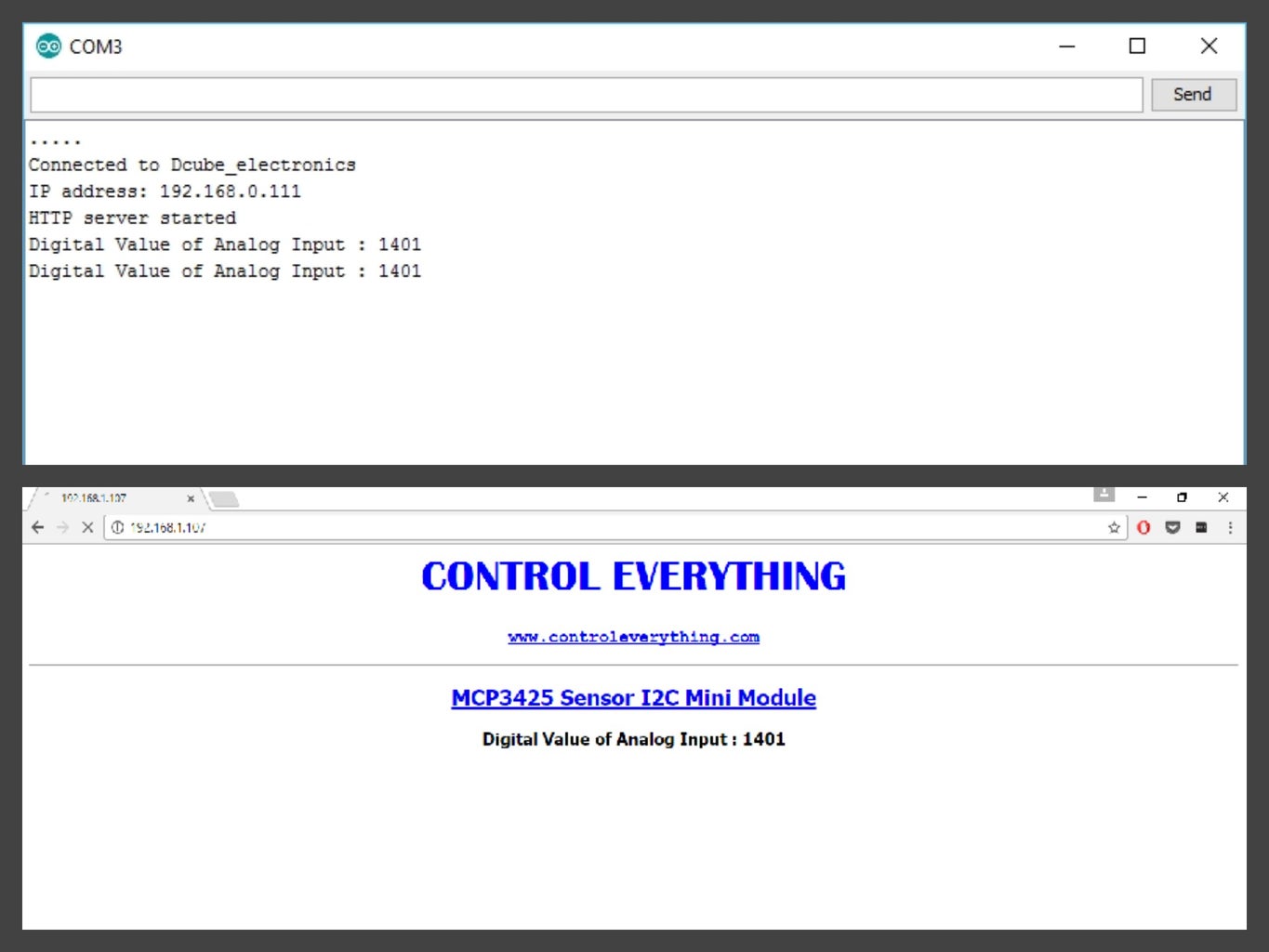
Copy the IP address of ESP8266 from the Serial Monitor and paste it in your web browser. You will see a web page with the digital output of analog input reading. The output of the sensor on Serial Monitor and Web Server are shown in the picture above.
Step 5: Applications and Features
The MCP3425 device can be used for various high accuracy analog-to-digital data conversion applications where design simplicity, low power, and small footprint are major considerations. Major Applications include Portable Instrumentation, Weigh Scales and Fuel Gauges, Temperature Sensing with RTD, Thermistor, and Thermocouple, Bridge Sensing for Pressure, Strain, and Force.
ADC converters enable accurate and reliable conversion performance in a range of applications such as communications, energy, healthcare, instrumentation and measurement, motor and power control, industrial automation, and aerospace/defense.
With the help of ESP8266, we can increase its capacity to a greater length. We can control our appliances and monitor their performance from our desktops and mobile devices. We can store and manage the data online and study them anytime for modifications. More applications include Home Automation, Mesh Network, Industrial Wireless Control, Baby Monitors, Sensor Networks, Wearable Electronics, Wi-Fi Location-aware Devices, Wi-Fi Position System Beacons.
Also, you can check our blog on Home Automation with Light Sensor and ESP8266.


