

Introduction: Gray Codes


This instructable describes what gray codes are and when they should be used. It also includes C source code that generates gray codes from 1 to 32 bits in length.
Definition:
A gray code is a number series in which one bit changes with each increment.
Here is a 2 bit gray code:
00
01
11
10
You may notice that it is different from the normal binary counting sequence:
00
01
10
11
In the normal binary counting sequence, when going from 01 to 10 (from 1 to 2 decimal) there are two bit changes, the first and the second bit change their state. Two bit changes also occur when going from 11 to 00.
You may notice that only one bit changes at a time in the gray code sequence above.
So, why would we care whether there is only a single bit transition or whether there are multiple bit transitions? It depends on the application...
Step 1: Example Use of Gray Codes


Example:
Here is an example where using the binary sequence gives us difficulties:
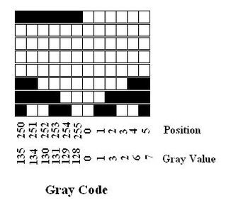
Suppose we wanted to read the position of a astronomical observatory Dome so we can be sure the dome opening is pointed so that the opening and the telescope are aligned. We could choose to read the position optically. We could print a strip of say eight black and white bars on the dome wall and read the dots using eight photoresistors. We could then read the position of the dome to within 1/256 of a full circle, or about 2 degrees.
See the emitter/detector circuit diagram below. To 'read' the position of the dome the microprocessor such as an Arduino would read the black and white bars on the dome wall, i.e. that bars rotate with the dome and the stationary reader does not rotate. The base of the 8 photodetectors are wired to 8 input pins of the Arduino. What coding sequence should we use?
Now suppose we had used the normal binary counting sequence to create our black and white bars for our photoresistors to sense. The problem we run into using the binary counting sequence is when we transition between one number and the next. Lets say our sensors are moving between the '255' position and the '0' position. As the transition occurs and the photoresisters are in between both numbers, a photoresistor or two might transition from '1' to '0' a little before the others. This could be due to a slight offset in the photoresistor's position or may be due to slight variance in the photoresistor's construction/chemical composition making it a little more sensitive than the others. For whatever reason one or more will transition at a different time than the others. During this time the reading from the phototransitors may go from 255 to 127 then to 0. If the motion is slow enough one may see many of these spurrious transitions between most numbers.
GRAY CODE to the Rescue!
A better approach would be to use a gray code instead of the binary code. Using the gray code, only one bit of the code changes with each increment. Therefore when between two positions of the code only one bit may fluctuate between the two positions. Therefore when between positions 0 and 1, the photoresistors may sometimes read 0 and sometimes read 1, however, both answers are still very close the actual dome position.
The problem with gray codes is that the decimal value between one position and the next do not differ by one. Software can easily resolve this using an array which includes the gray code (or its inverse). One can use the value read in from the photoresistors as an index into an array. The value of the array is the decimal position. Using the array one can then calculate the difference in postions.
Step 2: Gray Code Source
How to Generate Gray Codes?
I have included a sample 'C' source code that generates gray codes for any number of bits between 1 and 32 bits in the included file


