

Introduction: LEDs As Temperature Sensors


Using the Arduino microcontroller I have devised a method of using the voltage produced by a power LED to measure its own temperature to within +- 10 °C without the need for an external temperature sensor e.g. thermocouple, thermistor or digital sensor. In this instructable I explain the details of my idea as well as the code and how to implement this in an existing system. As far as I know I am the first person to implement this idea and I am planning on entering it into the Google Science Fair as I am 15.
An LED consists of a semicondutor pn junction. A pn junction will produce a voltage when exposed to light and heat in much the same way as a solar cell. However both temperature and light will affect the output voltage of the LED so to estimate the temperature the light level needs to be measured.
In my system I use a green LED as the light sensor. The value from both the power LED and the light sensing LED have to be inputted into a simple formula along with some constants to estimate the temperature. A small calibration sequence with different temperatures and light levels are needed to determine constants in the formula.
As of yet I have only been able to estimate the temperature of power LEDs that operate within the operation voltages of the Arduino.
In the next step I shall explain how to construct the calibration module.
Step 1: Constructing the Calibration Module


The calibration module will allow you to accurately control the temperature of the LED and measure it's voltage and light level. The readings obtained form the calibration will allow you to calculate the constants needed to estimate the temperature.
Things needed:
• Aluminium sheet (this is what the sensors, heater and power LED will be affixed to)
• LM35 temperature sensor
• Green LED (as light sensor)
• Plastic (1.6 mm thick for thermal isolation of light sensor from Power LED)
• 5 Watt 22 Ohm Power resistor (as heater)
• Power LED (running at 3.3 Volts)
First a piece of aluminium sheet approximately 55 mm by 30 mm must be shaped. Affix the power resistor, Power LED and temperature sensor to the aluminium plate with bolts or thermal adhesive if necessary.
Cut a 20 mm x 5 mm strip of the plastic to act as a mounting arm for the LED. This will prevent heat reaching the light sensor and affecting the light reading. Drill two 1 mm holes in the plastic to accommodate the LED leads. Bolt or glue this to the plate.
I made a modification to my original calibration module so that I could fit new LED s easily without needing to do any soldering. This involved shaping a piece of aluminium to clamp the LED onto the base plate and using copper tape on the calibration module as the electrical contacts.
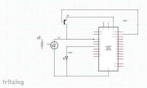
Step 2: Constructing the Circuitry

I used an Arduino Nano board as the brains of my device but I think any Arduino board could be used. I created a schematic and breadboard layout on Fritzing. To test my idea I simply made the circuitry on a piece of proto-board. The PNP transistor I used was a 2N3906.
Step 3: The Arduino Code
I am not going to go into detail as to how to program the Arduino boards as I am aware that there are already many instructables out there which have already explained this in great detail. I have attached a simple (and probably rubbishly written) piece of code for the Arduino which will hopefully allow you to perform a calibration of the LED.
The code averages out the reading over 20 readings to obtain a more accurate temperature reading. The voltage readings are in millivolts.
Attachments

Step 4: The Calibration
The calibration of an LED can be quite a lengthy process.
To do this I calibrated the LED over a range of temperatures and light levels. Using a power supply set to 7 volts I heated the module up using the resistor and let it cool down with the Arduino connected to your computer with the serial monitor opened in the Arduino IDE.
Step 5: Analyzing the Data From the Calibration


I copied and pasted the data from the serial terminal into excel where I performed some simple data analysis. The text to columns feature comes in handy when splitting the data into several columns using the space delimiting function.
Column order:
- Degrees C from LM35
- LDR voltage (delete this column)
- LED light sensor voltage
- LED voltage
- Calculated temperature done by the Arduino
Use this simple formula to change the variables to suit your LED setup.
Calc_temp = ((LED_voltage * LED_const) + (LED_light_voltage * light_const) + constant); Here are the values I used for the spreadsheet:
LED_const = -0.9
light_const = -0.15
constant = 4510
Step 6: Testing and Implementing
I have already included a piece of code that switches on the indication LED at pin 13 of the arduino nano when the calculated temperature rises above 50 degrees C.
In a real world application the light sensing LED could already be present in the form of an indication LED.

Participated in the
Unusual Uses Challenge

Participated in the
Home Automation


