

Introduction: Using the Arduino Uno to Program ATTINY84-20PU


Using the Arduino Uno to program ATTINY84-20PU (Newark item # 68T3783). This Instructable shows how to use the Arduino platform to work with physically smaller processors, such as the ATtiny84 (84/44/24), ATtiny85 (85/45/25), and ATtiny2313. This example is specifically for the ATtiny84-20PU processor (Newark item # 68T3783) but can be adapted for the others boards by selecting the appropriate board from the Arduino software (i.e., Arduino IDE) and modifying the pinouts as required.
Step 1: Configure the Arduino IDE Software


1) Ensure the Arduino software (aka Arduino Integrated Development Environment [IDE]) is NOT running on your computer.
2) Create new folder named "tiny" in your Arduino "hardware" folder
C:\Projects\Arduino\hardware\tiny
3) Download the Arduino-Tiny archive (ZIP-file)
http://code.google.com/p/arduino-tiny/downloads/detail?name=arduino-tiny-0100-0016.zip
4) Copy and paste the contents of the ZIP-file into the "tiny" folder.
5) Create a new file named "boards.txt" in the tiny directory using any text editor. Make sure to save as a text file (.txt).
C:\Projects\Arduino\hardware\tiny\boards.txt
6) Open the "boards.txt" file and the "Prospective Boards.txt" file using a text editor.
7) Copy board entries of interest from "Prospective Boards.txt" to "boards.txt". Or just simply copy the entire contents from "Prospective Boards.txt" to "boards.txt" like I did.
8) Save and close "boards.txt". Close "Prospective Boards.txt" (see picture for how the contents should look).
Step 2: Program the Arduino to Use As an In-System Programmer (ISP)


9 ) Open the Arduino software on your computer (aka Arduino IDE).
10) Select your Arduino board. I have the Arduino UNO but replaced the processor with a pre-programmed Atmega328P chip from Adafruit, which requires that I select "Arduino Duemilanove with ATmega328."
At this point, you should see additional "boards" listed, such as all of the ATtiny boards that as in your "Boards.txt". Do not select the ATtiny chip at this point. Select your Arduino board so that you can tell the Arduino that you want to use it as an In-System Programmer (ISP).
11) Select AVR ISP programmer by selecting [Tools] [Programmer] AVR ISP.
12) Upload the ArduinoISP sketch to your Arduino by selecting [File] [Examples] ArduinoISP. Once uploaded your Arduino will be programmed to be used as an ISP.
Step 3: Create Blink Sketch for the Attiny84


13) Open the sketch to be programmed onto Attiny84. This example uses the Blink sketch from the Arduino software.
[File] [Examples] [01.Basics] [Blink]
14) Edit the sketch so the LED pins correspond to the ATtiny84. That is, change "int led = 13;" to "int led = 0;"
Step 4: Configure the Arduino to Use As an ISP


15) Select ATtiny84 @ 1 MHz (internal oscillator; BOD disabled) by selecting
[Tools] [Boards] Attiny84 @ 1 Mhz (internal oscillator; BOD disabled)
(Note: Do not select a chip for use with an external oscillator unless you have one; it you do so, the chip will not work again until you have connected it to an external oscillator).
Your Arduino is now configured to be used as an ISP.
Step 5: Connect the Hardware


16) Disconnect USB/power from Arduino
17) Connect the Arduino Pins to the ATtiny84 pins.
Arduino 5V to ATtiny84 Pin 1
Arduino Pin 10 to ATtiny84 Pin 4
Arduino Pin 11 to ATTiny84 Pin 7
Arduino Pin 12 to ATtiny84 Pin 8
Arduino Pin 13 to ATtiny84 Pin 9
Arduino GND to ATtiny84 Pin 14
Arduino RESET to 10uF cap
10uF capacitor to GND
Step 6: Use the Arduino As an In-System Programmer (ISP)

18) Connect USB/power to Arduino
19) Upload modified Blink sketch to ATtiny84.
Note: An arvdude message appears - something about PAGEL and BS2 - but it is not an error. The program is uploaded successfully.
Step 7: Use the ATtiny84 As a Stand Alone Chip
20) Disconnect USB/power from Arduino
21) Disconnect hook-up wires between ATtiny84 and Arduino.
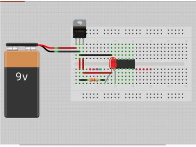
22) Hook-up ATtiny to run Blink sketch independently from Arduino:
a. ATtiny Pin 1 to 5V leg, which is the right most leg of the voltage regulator that I used with a 9V battery. Not not connect power source until all connections are made. This way you won't short anything. But just to be complete, the +9V goes to the input leg (left most leg) of the Voltage Regulator, the -9V to Voltage Regulator common leg (middle leg), and 5V output (right leg) to ATtiny Pin 1. But don't connect the battery yet.
b. ATtiny Pin 2 to long leg of LED (I defined this as Pin 0 when writing the modified blink sketch)
c. Short leg of LED to any end of Resistor (I chose 330 Ohm. Any resistor from 100 Ohm to 1000 Ohm should work).
d. Other end of Resistor to Ground
e. ATtiny Pin 14 to Ground
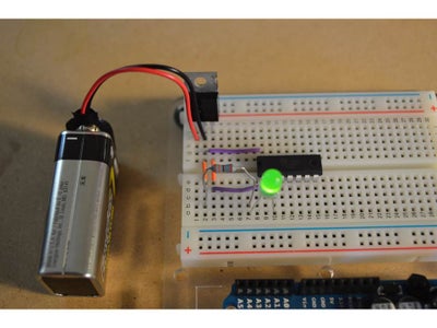
23) Now apply power to ATtiny84 by connecting 9V battery.
Step 8: Use All of the ATtiny84s Pins

I wanted to understand how to use each pin on the ATtiny84 so I added this as well:
24) Disconnect USB/power from Arduino
25) Tell the Arduino you want to use it as an ISP (that is, repeat step 2)
26) Download Blink sketch that uses all available pinouts (https://github.com/maltesemanTS1/ATtiny84-Blink-all-Pinouts.git) or modify your own sketch to use all pins (that is, repeat step 3).
27) Configure the Arduino as an ISP as shown previously in step 4.
Step 9: Use All of the ATtiny84s Pins


28) Hook-up ATtiny84 for Blink-On-Each-Pin sketch.
ATtiny Pin 1: 5V
ATtiny Pin 2: myPins[0]
ATtiny Pin 3: myPins[1]
ATtiny Pin 4: RESET pin
ATtiny Pin 5: myPins[2]
ATtiny Pin 6: myPins[3]
ATtiny Pin 7: myPins[4]
ATtiny Pin 8: myPins[5]
ATtiny Pin 9: myPins[6]
ATtiny Pin 10: myPins[7]
ATtiny Pin 11: myPins[8]
ATtiny Pin 12: myPins[9]
ATtiny Pin 13: myPins[10]
ATtiny Pin 14: GND
Connect ATtiny Pins 1 and 14 to 5V and GND, respectively.
Connect all other ATtiny pins, except ATtiny pin 4 (that;s the reset pin), to an LED
Connect a resistor (between 100 and 1k Ohm) between each LED and GND (actually, you can use just one resistor for all LEDs since this program blinks the LEDs one at a time. But it is safer to build with a resistor for each LED in case you mod the sketch at a later time.)
29) Apply power.
Step 10: Parts List
1. Arduino Uno (Digikey 1050-1024-ND)
2. 330 Ohm 1/4 Watt resistor (from resistor kit, Digikey RS125-ND)
3. 10 uF capacitor (from capacitor kit, Digikey P835-KIT-ND)
4. Breadboard ( Half-size breadboard, Adafruit PID 64)
5. 5V voltage regulator (Digikey 497-12404-ND)
6. 9V battery
7. jumper wire (Breadboarding wire bundle, Adafruit PID 153 or 22 awg solid core wire, Digikey A3051R-100-ND)
8. ATtiny 84 (ATTINY84-20PU, Digikey ATTINY84-20PU-ND)
9. 5mm LED (Digikey 754-1262-ND)


