

Introduction: Utah Utes LED Decor


Game Day Beacon! Go UTES!
Introduction
I started this project to learn about electronics, soldering, and circuits. The LED array is a pretty simple place to start because there isn't many elements. Soldering was a challenge for me at first but by the end of this I'm not too bad. I will share what worked for me; if I can do it, you can too.
Deciding to make an instructable probably doubled if not tripled the time it took me to complete this project. Taking endless amounts of pictures while constantly thinking about how I will explain what I'm doing later. My goal, besides winning the Green Design contest of course, is to create an instructable that someone can learn from on every page. So, if you could care less about college sports but don't know the difference between transformer and a resistor than you can still learn something. I've found the best way to learn something really well is to learn it well enough to teach it to someone else.
I learned many things from designing and building this project. Mistakes were made in this trial and error process. I learned new skills like anti-sodering from fixing my mistakes. I also thought of different approaches to solving problems that I'll explain under
Hindsight sections. If you know a better or simpler way to do something I encourage you to comment. Or if your confused on how I did something please ask.
Green Design
Designing the Utes U to be as Earth friendly as possible was a challenge. Some things I wanted to do like using solar power or an LDR (light dependent resistor) to have the LEDs dim when the lights are on to save power, I couldn't get to work with so many LEDs. However, the wood I used is recycled from an old cedar fence. Every material that is used throughout the project such as, glue, paint, wood putty the best eco-friendly options will be discussed. I will also show how to calculate how much power and energy is consumed. With that you'll be able to calculate the power and energy consumed for anything else.
Let's pretend Utah doesn't do well in the Pac 12 or my wife doesn't get accepted to their medical school next year and I have to transfer schools and find a new team to root for. Everything in the U can be taken out and be used in other projects. Even the U itself can be reused in a fire to roast a marshmallow.
Tools & Supplies
Resistors Ω 8 - 1 Ω 1 - 43 Ω
Transformer - 12V 15W 1.25A Power Supply
LEDs - 5mm
Mounting Bezel and Ring for 5mm LEDs
Perf Board (1-7/8" x 2-3/8" )
Electrical wire - 2 colors
Electrical tape
Solder iron & Solder
De-soldering Braid
Button on/off
CPS-PT Pigtail CPS Power Adapter Cable (Female)
Router
Straight Plunge Router Bit
Jointer
Planner
Wood Glue
Clamps
Measuring tape
Sandpaper
Drill Press or Hand Drill
Drill Bits
Band Saw or Jig Saw
Pencil, Markers, Eraser
Screws 4 - #6 1" & 4 - #4 1/4"
Attention!
Please read, understand, and follow instruction manuals for all power tools. Wear your safety glasses
Step 1: Green Design


What does it mean to be green? Here is a small list of examples;
-Products that are made from recycled or salvaged materials
-Conserves natural recourses such as oil (plastic)
-uses less water or energy
-Products that don't use or create toxic materials or emissions
-Low VOCs & HAPs
-The product is easy to recycle
-The product provides a long service life (require fewer replacement cycles)
HAPs Hazardous air pollutants
VOC is an acronym for volatile organic compound. These compounds react with atmospheric ozone, along with particulates, to form smog. Smog is thought to be a major contributor to air pollution and health problems, such as asthma.
Designing with Green Materials
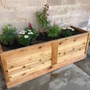
I started with salvaged cedar.
Selecting a "green" indoor adhesive pick one with low VOCs or formaldehyde-free adhesives.
Titebond wood glue CONFORMS TO ASTM D-4236. titebond.com proudly shows data for all their adhesives because they are high above the standards.
Selecting a "green" wood putty I think woodwise.com says it best about their product:
WOODWISE wood fillers were developed for water and solvent based stains and finishes. These environmentally friendly wood fillers contain no harsh solvents, and do an outstanding job of filling cracks, nail holes, gouges and broken edges.
Eco Friendly Data for their putty can also be found on their website.
Selecting "green" electrical wire look for halogen-free RoHS-compliant materials, PVC Free (The production, use and disposal of PVC release hazardous chlorine-based chemicals such as dioxin), and Lead Free.
That is exactly what Totoku electrical wire offers.
http://www.totoku.com/products/cables/cat8/environmentally-friendly-type-electric-wire.php
Selecting "green" solder look for, low VOC, halogen-free, lead-free products. Check out Alpha cored wire.
http://alpha.alent.com/Products/Cored-Wire
Or make your own with an instructable by burningsuntech
Selecting "green" paint zero-VOC paints that also use VOC-free colorants, are free of vinyl and other plasticizers and include no toxic biocides. See if Green Seal, Greenguard and Ecolabel test your paint to ensure that they have met the highest standards of eco-friendly performance. Or you use Natural Casein paints are made primarily from milk proteins, lime, and non-toxic pigments.
I used Glidden from HomeDepot because they have Utah University Crimson Red. They say it is Low VOC and eco friendly on their website but aren't as open with details like the materials listed above. Maybe not the best option.
The "trim tray" bucket I used to hold my paint in is biodegradable and the paintbrush is reusable. I'm going to reuse the stick I used to stir the paint to fix a hole in my sheet rock.
Selecting "green" screws look for RoHS, WEE, and ELV Compliant.
Selecting "green" perf board look for look for RoHS, WEE, and ELV Compliant.
I soldered the LEDs without cutting the leads so they can easily be reused in the future. All the wire, resisters, LEDs can easily be removed/replaced with a soldering iron and anti-soldering braid. The transformer can be unplugged and used in other projects while the U isn't in use.
I added a button that turns on/off the LEDs to reduce power, although I think the transformer may still use some power.
Step 2: LED Array


Vs = 12V Voltage source
VL = 2V Voltage drop or Forward Voltage
I = 100mA Current (mili Amperes) 1mA = 0.001A
To figure out how many LEDs go in each series you need to know your power source voltage and the voltage drop, should be able to find voltage drop where the LEDs are purchased. It is also called Forward Voltage:
Take the Vs = 12V and divide by the VL = 2V which is 6 in this case.
Let's say you had a 9v power source: 9V/2V = 4.5 but you can't have a half of an LED so round down to 4 LEDs
Let's say you had a 3v power source: 3V/2V = 1.5 but again you can't have a half of an LED so round down to 1 LED
Basically if each LED needs 2V, how many can you have before there isn't enough voltage to light one up?
Now, I have 52 LEDs in each series i'm going to use 6 LEDs. 52/6 = 8.6 round down to 8
So, I need 8 - 6 LEDs in a series but I've only used 48 of the 52 LEDs.
Leaving 1 - 4 LEDs in a series
Next let's calculate the resistance we need for each row in series using the equation in the photo (Ohms Law).
VL = 2V + 2V + 2V + 2V + 2V + 2V = 12V (the three LED voltages added up).
R = (12V -12V) / 100 mA R = 0 For each 6 LED series
R = (12V - 8V) / 100 mA (100 mA = (10 * 10^-3) ) R = 40 but the closest resister is 43 for the 4 LED series
52 LEDs @ 4 Lumen each = 208 Lumen
52 LEDs @ 1200mcd each = 62,400 mcd ---> 624 mc
Red 5mm LED RL5-R12120 superbrightled.com
Forward Voltage 2.0V
LED Package 5 mm (T-1 3/4)
4 Lumen
Maximum Forward Voltage 2.4V
Millicandela 1200mcd Brightness of the LED at the given current, mcd = millicandela
Peak Forward Current 100mA
Power Dissipation 85mW
Reverse Voltage 5V
Total Power Consumption 0.12 Watts
Tube Diameter T1-3/4
Viewing Angle 120 degree
Wavelength 625 nm
Thanks http://www.ledcalc.net/ and superbrightleds for the photos
I bought the LEDs, Mounting Bezel and Ring, and the 12V transformer at superbrightleds
FYI a transformer converts the 120 V alternating current (AC) to 12 V direct current (DC).
Step 3: Power & Energy


I really wish I could write equations in these boxes... Instead i wrote out all the equations, I hope my hand writing is legible.
Fix Your Power Bill!
Step 1 Lighting:
Consider changing light bulbs to CFL or LED from incandescent. I'd pick LED if I had a choice even though they are the most expensive. CFLs need special disposal because of the mercury they contain.
For 800 lm (brightness) the following uses
Incandescent = 60 w
CFL =13 w
LED = 11 w
Turn off lights when they aren't being used. Install dimmers.
Step 2 Vampire Power:
Many electronics and small appliances continue to draw power even when they are turned off. The average household spends $100 per year to power devices while they are off (or in standby mode).
Unplug devices when they aren't in use. Hook up tv, dvd player, xbox, computers, stereos, and coffee makers to a power switch and switch it off so the appliances don't use standby power.
Step 4: Prepare Wood for Glue

The purpose of this step is to create smooth surfaces.
When running something through the planer try to stand to the side. it is possible for a knot to break off and shoot out.
Run each piece right after each other, butted up end to end, then run a piece of scrap butted up against the last piece. This is so all the parts go through smoothly. Try to use the width of the planer too so that the cutting tool dulls evenly.
This may be accomplished using a belt sander too.
Step 1:
Check for nails, screws, staples or anything in the wood that could damage the tools. Usually you would want to check for cracks in the wood but because we are gluing a stack together it isn't necessary.
Step 2:
Run each side through the planer, taking just ~1/16" each pass. ( " = inch)
Step 3:
If necessary, take more passes to remove imperfections. Additional planing may be necessary if the wood has a little bow that was not removed during initial planing.. Smooth, flat surfaces are required for glue.
Step 5: Stack and Glue


Gluing the pieces together is going to make the U a free-standing block. Each slate is ~1/2" thick; slightly less after being planed. I stacked 5 slates together with an end product of 2-1/8" thick. The slates are only ~5" wide. The U is going to be 9-1/2" requiring two stacks of 5.
Step 1:
Apply glue to both surfaces evenly. I used a glue bottle roller but a scrap stick or even a finger works just a well.
The glue should be the thickness of paper, you don't need a lot of it.
Step 2:
Put the gluey surfaces together aligning 1 side and 1 end. The better aligned they are the easy it will be to joint later.
Step 3:
Apply clamps, alternating sides to distribute pressure.
Leave clamps on for 30-45 minutes. (read instructions on glue)
Step 4:
Repeat steps 1-3 until you have 4 stacks with 2 layers.
Repeat steps 1-3 to make 2 stacks with 4 layers
Repeat steps 1-3 using a stack of 4 layers with a single layer.
End result - 2 stacks with 5 layers
Step 5:
Joint the side of each stack that was aligned together. Take off as little as material as possible.
When jointing use equal pressure across the whole board while running it through the blade. Be square with the fence.
Jointing is doing the same thing the planer did, which is to clean up a surface for gluing.
Step 6:
Repeat steps 1-3 but align the joint and 1 end as best as possible now. Adjust clamps, push down on one side to ensure joint is as flush as possible. If the two pieces end up too uneven, a lot of material will be removed at the planer, requiring more slates to obtain the required thickness.
End result will be 1 big stack with 5 layers
Step 7:
This is a good time to glue together the back panel using these steps. It is 2 slates wide 1 layer thick
Step 8:
Let the glue dry for a couple hours before running both top and bottom through the planer.
Don't worry about the sides right now.
Step 6: Layout


Everything needs to accurately marked on the block. The side that has the layout on it will be the back of the U.
Step 1:
Using a square and a straight edge, create reference lines on the block. Basically create a square corner and measure from the corner to mark where the lines go. Accurately draw the outline of the U.
Step 2:
Measure 1/4" inside the U draw another U.
This line will act as a guide to remove material 1/4" deep with the router.
Step 4:
Measure 5/8" in from the outside U to create another U.
This U will be a guide for the LED holes.
Step 5:
Mark center for each LED. BE ACCURATE - if they aren't straight the final result won't be impressive.
Check "Green Design" step for my placement of the LEDs
Hindsight
Doing the layout directly onto the cedar was tricky because the grain kept giving the illusion my lines weren't straight. I wouldn't outline the U in the marker. It made the line inaccurate to measure from and cut out. 52 LEDs is overkill as it creates a very bright display.
Step 7: Drill Holes


The holes are for the LEDs to go through.
Pull back out often to remove wood.
Step 1:
With a 11/32 drill bit and the drill press - make some holes!
If you have forstner bits... USE THEM!
clamp down material nice and tight so there is no wiggle room. Align drill bit in the center of the mark. Remember in the corners it needs to match up two ways.
Cedar is soft but don't rush it, make them straight and perfect.
Use a piece of scrap wood underneath the U to drill into to reduce blow out
Step 2:
Repeat 52 times
Step 8: Remove Material With Router for Back Panel


Material is being removed so a back panel can be screwed on to hide the electrical wire.
Using the router "on top" of the material (as opposed to using a router table) the bit is spinning clockwise.
Cedar is really soft and in the end it doesn't matter which way you router. However to try and make straight edges one direction seemed easier than the other depending on the grain. Remove a little material at a time.
Step 1:
Using a 1/4" straight plunge router bit. Set depth to 1/4".
Clamp the U down
I placed the bit into one of the holes so I didn't need to "plunge" into the material.
Remove all material inside the Middle U.
Step 2:
I used two pieces of printer paper taped together and a coloring stick to make an outline of the back.
Step 9: Remove Material for Wires & Perf Board


Red lines represent the positive end of each LED series going away from the perf board. The blue lines represent the negative wires returning to the perf board. Outlining this I also meant to leave places for the screws to go for the back panel like I did with the perf board. I forgot. The back needs something to screw into and there needs to be a space for all the wires to hide. That is why it looks like a ant farm.
Step 1:
Outline the material to remove.
Set the depth to ~1/2" (so add ~1/4" to the last setting)
Remove material
Step 2:
Perf board needs to be a little deeper with breathing room on the bottom. Space for the circuit, soldering, and wires.
Set the depth 3/4"- 7/8" (add ~1/4" to last setting)
Remove material
Step 3:
This was trial and error making everything fit properly. I've had to go back and remove a little material because wires weren't quite long enough. I need to remove some material still at the perf board because the space between the wires and the back plate isn't thick enough where all the wires come together. I've had to remove material under the perf board to connect the LEDs underneath there.
Step 4:
Use a piece of 100 grit sand paper to "ease" the edges and remove little flurries.
Step 10: Cut Out Back Panel


Step 1:
Plane the back panel to the desired thickness 1/4". Remove any cracks that might be in the ends of the cedar. It isn't very thick and a crack will likely destroy the U once its cut out.
Tape the outline to the cedar.
Step 2:
Set the guard just above the material for safety.
Make plenty of relief cuts stopping before the line. Cut out the U.
To get inside the cut out little triangles at a time until there is enough space to cut out the U
Step 3:
Trial and Error
Mark with a pencil or marker where the back piece doesn't fit into the block U.
Trim until it fits
Where it is just a hair too big use a block sander to remove a little material.
Step 11: Fix It!


If you're careful and make space for your wires you can skip this step.
This can be applied to anything that needs to be glued back together.
The back panel is not very strong and while trying to force it on I broke it. Because of the angles it is impossible to clamp.
Step 1:
Use glue like before.
Spread it on both sides
Step 2:
Firmly press the tape on one side of the break.
Step 3:
Stress/Pull the tape over the crack and firmly press down.
Step 4:
Repeat across the whole break then carefully flip it and do it on the back
Step 12: Drill Holes for Power & Screws


Step 1:
Decide where the Power cord, Button, and Screws will all go. I only had a couple options, I marked those places with Xes then measured from the outside to remake it on the back panel.
Step 2:
For the Power Cable I didn't want it to go all the way through.
First drill a 9/32" hole
Drill with a 27/64 bit from the inside of the back panel stopping before the end.
Use a pencil to mark where the power cord goes. Drill down a inch or so to make room from the cord.
Drill another hole near that hole so the wire has space.
To avoid going through, decide how deep you need to go, measure from the tip of the drill bit and wrap a piece of tape around the drill bit.
Step 3:
Use 3/32" drill bit to pre-drill holes for #6 1" screws
Then counter sink for a nice finished look.
Step 4:
The hole for the button is 3/8"
Step 13: Cut Out the U


Step 1:
Set the guard to the proper height. Make plenty of relief cuts but stop before the line. Clear away scraps often.
Step 2:
When coming to a relief cut slow down. the blade seems to jump a little when it reaches it but will make a smooth cut if your going slower. To trim a little piece, put the U up to the blade like in the last picture and slowly ease into the cut.
Step 14: Putty & Sand


Around the holes I had some blow out. I had a crack where my glue joint wasn't perfect, knots to fill in.
Step 1:
Fill in dents, holes, knots, cracks, and all other imperfections. Around the holes, apply putty then stick a pencil through the hole
to remove any excess putty and prevent the hole from clogging.. Let the putty dry according to the specified time provided on the bottle.
Step 2:
Use 80-100 grit sand paper and sand all the parts. Using an orbital sander be sure not to leave it in one place too long because it will create dips and bumps in the U. Also, when sanding the sides be sure to hold the orbital sander square.
The inside of the U and the corners need to be sanded by hand. Use a block with a piece of sand paper wrapped around it.
Step 3:
You may need to repeat puttying around the holes a couple times. It will pay off in the end when the bevel fits in there just perfect.
Step 4:
You can sand to 120 grit but it isn't necessary if you're going to paint your product. If you're planning to stain the product, I'd recommend going to 150 grit. I only used 100 grit sand paper and it turned out great.
Step 5:
Don't forget to putty the back panel.
Step 15: Perf Board


Perfboard is a material for prototyping electronic circuits. It is a thin, rigid sheet with holes pre-drilled at standard intervals across a grid. I'm using it as a central point to connect my series LEDs into Parallel with each other. This is also a great place to connect all the resistors.
Step 1:
Outline where everything is going to be connected.
Use 1/16" drill bit to widen holes for the electrical wire to come through
Step 2:
Follow the outline with solder. I found it easier to add a drop let it cool then come back to connect two drops.
Step 3:
Stick the resistors through their marked holes. Use a piece of tape to make sure they don't fall out when you flip the perfboard over. Solder and trim the resisters. They aren't directional like LEDs so it doesn't matter which way they go.
Connect the resisters using the same drop technique to the negative line.
Step 4:
Put the perfboard into the U and pre drill into the wood for the screws. Using the same 1/16" drill bit as in step 1 or do it all at the same time. Put the perf board in its place, drill the holes through the perf board and into the wood.
Step 16: Make LED Series Strips


Step 1:
Measure the length of each wire. Measure how much is needed to reach from hole to hole. If you have too much it won't fit underneath the back panel and if you don't have enough the LED won't reach the front of the U.
Step 2:
Use wire cutters to expose the metal inside the wire.
I use a pair of needle noose pliers to hold the other end of the wire while I pull with the wire strippers.
Step 3:
Warm up the solder Iron and connect 8 - 6 LEDs in a series & 1 - with 4 LEDs . LEDs are directional so they will only turn on if the positive is connected to the anode and the negative is connected to the cathode. To solder i lay the wire and LED down next to each other. I get a little bit of solder on the LED so i can kind of pick it up with the solder iron to place it on top of the wire. I apply solder trying to make it smooth and pretty. I flip it over and solder the wire so it doesn't fray. Be careful though if it gets to hot the LED lead will come undone.
Or, try putting solder on the wire first. With a free hand now you can hold the LED to the wire. Reheat the solder on the wire then place the LED to the hot solder. Wait for it to cool maybe blow on it a little and viola.
Step 4:
Because I left my cathode & anode long the possibility of the leads touching after being stuck down the hole is very likely. To ensure that they don't touch causing them not to turn on put a piece of electrical tape on either the anode or cathode.
If the cathode & anode are cut short and solder is applied closer to the LED the electrical tape can probably be skipped.
Step 5:
Its a good Idea to label each LED series and where the positive and negative leads go. It becomes a rather overwhelming mess.
I labeled them with those paper clips first but later used a piece of tape wrapped around the wire.
Step 6:
Stick the wires through all the holes and take it so it doesn't fall out
Make sure that the black wires match up to the correct resister.
On the back of the perf board solder wires with solder to the negative and positive lines of solder.
Step 7:
Solder the power jack to the button.
Measure how far it is to the power hole to the button hole.
With wire strippers, strip the positive and negative wire in the middle of the wires about 1/8" long
On the button there is two metal places to connect power. Solder the positive to one and the negative to the other.
Put solder on the wires first then reheat it and connect it to the button is a pretty easy way to do it.
Step 8:
Connect the power to the perf board.
Step 17: Paint


I used a roller where I could because I didn't want brush strokes, just a smooth crimson red surface. The bucket I used wasn't meant for a roller but it still worked
Step 1:
mix the paint and pour some into the the bucket. Dip the roller into the bucket and roll out the excess onto the side until there is a uniform amount of paint on the roller. Roll it onto the U evenly going in different directions to remove little gobs and lines.
Step 2:
Reapply paint when needed. Stir paint frequently. After rolling the sides check the front and back for excess spilling over. Use a brush dipping it in the paint and removing excess, to paint the corners and the inside of the U.
Step 3:
On the back the only thing that needs paint is the very back and inside wall where the back panel sits.
Step 4:
Paint the back panel. Wait for the paint to dry
Step 5:
Do a second coat.
Step 18: Fix It - Anti-Soldering & Multimeter

Step 1:
Cut a small piece of the unsolder braid. I use a pair of self locking pliers to hold the piece of braid. Apply heat to the place where solder needs to be removed.
Step 2:
when the solder is gooey remove heat and place the braid on top of the solder. Reapply the tip of the soldering iron to the braid pushing it into the solder. The braid should easily absorb all the solder.
Step 3:
When removing a resistor or any through hole electronic apply heat all around the wire with the braid.
Multimeter
Don't know what lead is the cathode and which is the anode? No Problem!
Step 1:
Plug in the wire to the correct places and turn it on to resistance
If you plugged it into the wrong hole it will usually beep or something.
Step 2:
When the Positive led is touching the cathode ( - ) while the negative led is touching the anode ( + ) nothing happens. There isn't a resistance.
If the Positive led is touching the anode ( + ) and the negative led is touching the cathode ( - ) a you'll get reading for resistance.

Participated in the
Instructables Green Design Contest


