

Introduction: VGA Tetris With Arduino Uno
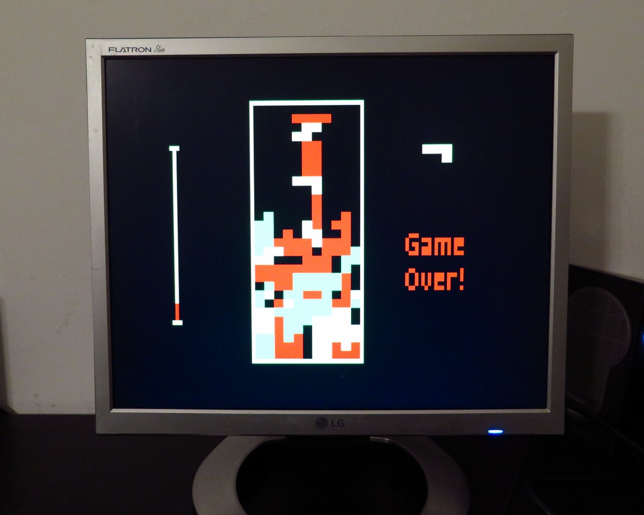


I have reproduced a color version of the classical game TETRIS running for a VGA monitor, by means of a bare Arduino Uno and few other components.
The goal was to avoid any special shield or supporting IC. The only needed components are four buttons, few resistors and a DSUB15 connector.
I used Arduino IDE 1.6.4. and the VGAx library done by Smaffer and publish on GitHub here.
This library allows to use four color with a resolution of 120 x 60 pixels, not many but enough for this retro-game. I optimized the graphic for a 4:3 VGA monitor. The wide-screen is too deformed at the moment, but I plan to write a version where you can choose the monitor type.
More details can be found in this Arduino forum.
Step 1: Schematic and Code

To reproduce this game you need first to download the code. Version with sound here.
Then you need the VGA libraries.
You can immediatly upload them on an Arduino Uno. Some warnings are "normal", for instance, my (Italian) version says:
Lo sketch usa 10.384 byte (32%) dello spazio disponibile per i programmi. Il massimo è 32.256 byte.
Le variabili globali usano 1.959 byte (95%) di memoria dinamica, lasciando altri 89 byte liberi per le variabili locali. Il massimo è 2.048 byte. Poca memoria disponibile, potrebbero presentarsi problemi di stabilità.
Do not warry if the global variables memory uses up to 95% of space. In my experience there are no stability problems.
If you don't get any other error message, you can build your own VGA shield.
Needed components:
- an Arduino Uno Rev 3 - original or a clone, but original is better :-)
- a DSUB15 connector (i.e. a standard 15 pin VGA one)
- resistors: 2 x 68 Ohm; 2 x 470 Ohm and 4 x about 1 to 2 kOhm
- four buttons
- facoltative: a matrix board or just some wire and pins
- facoltative: a speaker.
Connect the parts as shown in the upper schematic.The speaker must be connected to pin A0.
If you have done everything properly, you should be ready to play!
Enjoy!
Step 2: Adding a Case With Buttons


Finally I have put the Arduino board and connections in a wood box. You can see an intermediate step with all the holes drilled in the box and the button inserted, and finally the outer and inner view.
The Arduino connections are exactly the ones shown in the first schematic.


