

Introduction: Virtual Reality Teleconferencing Device With Google Cardboard


Virtual Reality Teleconferencing Device with Google Cardboard
Created by John Choi | 2015
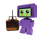
This project is a video teleconferencing device with two webcams for stereoscopic vision placed on top of a 3-axis motorized platform, controlled by a head-tracking head mounted display.
Note that virtual reality in general is still a technology in development, and there are many areas for improvement. Specifically, there is a noticable delay between head rotation and computer response, and sending video and angle information over a network only exacerbates this issue. Also, the servo motors used in this project occasionally "jitter," causing the device to rotate in small increments without input. Ultimately, the device demonstrated here is very finicky at best and should not be considered a completed product in terms of either reliability or usability.
In order to build and run this project, you will need rudimentary electronics skill, access to 3D printing, and the ability to use a personal computer (Windows 7 or above). Estimated time for construction is one week, and expected cost for this project is roughly 60 USD (variable depending on what parts you already have).
Step 1: Parts & Software


You will need the following parts for this project: (Sample links provided. Substitutes may be used.)
- VR Compatible Smart Phone (Android)
- Google Cardboard (I used a plastic variant.)
- 2 DifferentWebcams (They must be different as Windows cannot recognize two of the same webcams.)
- 13x 1/2" 4-40 Screws
- 7x 3/8" 2-56 Screws
- 3x Standard Servos
- Mini Camera Tripod
- 3D Printed Parts
- Small Breadboard
- 12x Jumper wires
- USB A to B Cable
- AA Battery Holder
- 4x AA Batteries
- Arduino UNO
You will need the following software for this project:
- Processing 2.0 (Optional. You need this if you want to change the source code.)
- TrinusVR
- Arduino
- Skype
- VRTD
Step 2: 3D Printing


Go to this GitHub repository: (https://github.com/johnchoi313/Virtual-Reality-Teleconferencing-Device)
Click on the download ZIP button, and extract the downloaded files. Navigate to the CAD folder. Here, you will find all necessary files to 3D print in STL format. Go ahead and 3D print all 4 parts in whatever colors you please.
If you do not have a 3D printer, I recommend using a 3D printing service like 3D Hubs to find a local 3D printer in your area. Expected print time for all parts is around 4 hours.
Step 3: Assembly


There are 3 servo motors to attach to 4 3D printed parts. This can be done in the following steps:
- Attach the servo motors to Parts 1, 2, and 3 as shown. Make sure the orientation of the servo is correct! Secure the servo motors by using the 4-40 screws.
- Attach the the servo horns to the servo motors at their 90 positions. You can make sure the horns are attached in the correct rotation by rotating the motor 90 degrees forward and backward.
- Attach the Part 1/servo piece to the bottom of the Part 2/servo piece. Secure the connection in place using two 2-56 screws.
- Attach the Part 2/servo piece onto the U-shaped portion of the Part 3/servo piece. Use three 2-56 screws on the servo horn side of the Part 2/servo piece and one 4-40 screw on the other side.
- Attach Part 4 to the servo horn on the top of the Part 3/servo piece.
- Attach the Mini Camera Tripod to the bottom of the Part 1/servo piece.
Note: Due to the nature of 3D printing, it is possible that the screws may not fit. If this is the case, use a drill to make the holes larger until the screws do fit.
Step 4: Electronics


An Arduino UNO is used to control the 3 servo motors, which are powered with 4 standard AA batteries.
If you've had any experience with RC servomotors, you'll know there are 3 pins for each servo: red/orange for voltage input, black/brown for ground, and white/yellow for signal. Because 3 standard servo motors drives more current than the Arduino UNO is able to handle, we will need a separate power source (in this case the 4 AA batteries). Also, as this device has 3 degrees of freedom, there are 3 digital pins to consider: one to control the base servo (Yaw), one to control the middle servo (Pitch), and one to control the top servo (Roll).
Create the electronic wiring as shown in the Fritzing Diagram above. Note that the servos are wired in parallel.
Step 5: Uploading Arduino Code


This project runs on the Standard Firmata protocol. In essence, Standard Firmata is an easy to use interface with the Arduino board that allows continuous real-time control through an application on another device, such as Processing on a laptop. Do the following steps to setup Standard Firmata:
- Open the Arduino IDE and connect the Arduino UNO to your computer using the USB A to B cable.
- Click on File->Examples->Firmata->StandardFirmata. This will load the necessary example code onto the Arduino IDE.
- Now, click on Tools->Board->Arduino UNO. This will change the board type so that the IDE knows what hardware it is working with.
- Finally, click on Tools->Serial Port->(Serial Port Name). This will set the Arduino IDE to the serial port where the Arduino is connected (usually, the Serial Port Name is something like COM# on Windows).
- Upload the Standard Firmata code onto the Arduino by clicking on the arrow button next to the check mark on the upper left of the Arduino IDE. If there are no glaring orange errors in the Arduino IDE log, then the code has been uploaded successfully onto the Arduino board.
You can test the Standard Firmata protocol and make sure it works by using the Firmata Test application. You can download this here. Run the Firmata_Test executable, and click on Port->(Serial Port Name). The Serial Port Name is the same one used to upload the code in the Arduino IDE. After a few seconds, you should see a lot of pin information appear, which can be controlled in real time. In particular, we are interested in pins 8, 9 and 10. Change their type to "Servo" and adjust their sliders to see that they work as expected.
Step 6: Setting Up TrinusVR for Google Cardboard


The modern virtual reality device is essentially a head-mounted screen that displays stereoscopic visuals while tracking the user's head rotation in real-time. The continuous feedback between the user's head movements and the stereoscopic contents of the display generates an illusion of being in another place, hence the name "virtual reality."
For our purposes, we will be using an Android smart phone locked inside a Google Cardboard to generate both the stereoscopic display and the gyroscopic head tracking to produce the illusion of virtual reality.
Because our project is primarily PC based, we use TrinusVR to stream video and head-tracking data from the Android smart phone to the main computer. Note that you will need TrinusVR installed on both your phone and your computer for this to work. More documentation on how to setup and use TrinusVR can be found here.
Note: It is possible to use another virtual reality device such as the Oculus Rift. It will be compatible with the Virtual Reality Teleconferencing Device as long as the head-tracking data can be used to control the computer's mouse movements.
Step 7: Running the VRTD Software


This project uses custom software written in Processing 2.0 to remotely control the Virtual Reality Teleconferencing Device (This software can be found in the VRTD link in Step 1). This software is separated into two parts: VRTD_sender and VRTD_receiver.
In summary, VRTD_sender is used on the computer connected to the virtual reality device. This software tracks mouse movements generated by head tracking, and streams it to a specified IP address. This IP address belongs to a second computer, which is in a remote location running VRTD_receiver. VRTD_receiver stereoscopically displays video data from the left and right webcams, and also controls the rotation of the Virtual Reality Teleconferencing Device according to the data sent from VRTD_sender. The stereoscopic webcam data can then be streamed through a video chat program like Skype with screensharing enabled.
To do Virtual Reality Teleconferencing, do the following steps:
- Have 2 Windows computers ready (Computer A and Computer B).
- Hook up Computer A with the Google Cardboard, and run VRTD_sender.exe.
- Hook up Computer B with the Virtual Reality Teleconferencing Device, and run VRTD_receiver.exe.
- Set the Left and Right Webcams and the Arduino Serial Port in VRTD_receiver.
- Run Skype on both computers and initiate a video call with screen sharing.
- Enter the IP Address of Computer B in VRTD_sender.
- Wear the virtual reality display, which controls the mouse, and hence the motors on Computer B.
Note: It is possible to use the Virtual Reality Teleconferencing system on one computer. If you wish to do this, run VRTD_sender and VRTD_receiver on the same machine and use 127.0.0.1 as the target IP address.
Step 8: BONUS - Improved Control Software
In the previous step, instructions to setup software were given with VRTD Sender and VRTD Receiver, powered by Processing. However, some limitations must be considered in the fact that some of the parts of the original system were proprietary, work only on Windows, and have tremendous lag.
To address these issues, an awesome user by the name of volkovmqx decided to make his own software to make the Virtual Reality Teleconferencing Device work on any platform (Windows, Mac, and Linux), and because he's awesome, he's released it for free on GitHub. Some details about the new and improved software:
- The Streaming server /StreamingServer that uses CVLC and HTTP MJPEG.
- The Position Server /motionServer that grabes REST Requests from the Phone Gyroscope and Send them to the Arduino Through Serial. Technologies used : Python, Tornado and PySerial.
- VR ready Mobile App /mobileApp , made by Ionic so it can be used on Iphone or Android, that consume the two Streams and send the Gyroscope data to the WebServer Created by /motionServer .
- Arduino Code /Arduino to move the Servos to the desired place.
The video above shows the new software in action with a plastic Cardboard.
Step 9: Conclusion

Congratulations! If you got to this page while building everything along the way, you should now have a fully functional Virtual Reality Teleconferencing system. You can now use it to immerse yourself in places across the world without actually having to be there.
This project is part of the Phone Contest, so if you liked it, please be sure to press the "Vote" button on the upper-right hand corner on this page.
If you wish to expand upon the Virtual Reality Teleconferencing Device, feel free to do so! All the necessary CAD files and Processing source code made specifically for this project have been released under a free Open Source License.
Happy Virtual Reality Teleconferencing!
-John C.
Video Intro Music Credits:
"Sancho Panza Gets a Latte" by Kevin Macleod (incompetech.com)
Licensed under Creative Commons: By Attribution 3.0 http://creativecommons.org/licenses/by/3.0/
Second Prize in the
Phone Contest


