

Introduction: Wallbots: Autonomous Magnetic Robots That Traverse Vertical Surfaces


The robots are outfitted with several light sensors, allowing them to respond to simple user interactions. My implementation supports 3 robot 'personalities', which can be changed by covering the topmost light sensor:
Red robots move fast, going towards objects (such as human hands or other robots)
Green robots move slower, turning away from objects
Yellow robots move the slowest, and stop completely when motion or objects are detected
This instructable details my first prototype. In the future I plan to build in more complex, autonomous behaviors. I will use these robots to engage people in public spaces such as elevators or hallways. In doing so, I hope to facilitate creative interaction between people and technology in mundane, everyday settings.
Stacey Kuznetsov
stace@cmu.edu
Human Computer Interaction Institute
Carnegie Mellon University
for Making Things Interactive, Spring '09
*** UPDATE ***
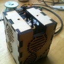
I recently made another version of this project using continuous servo's from sparkfun and a custom-cut PCB. The new robot is much much sturdier:
Step 1: Gather Materials


To make one robot, you will need:
2 servo motors http://www.rctoys.com/rc-toys-and-parts/DF-SRV-6G/RC-PARTS-DRAGANFLY-SERVOS.html?utm_source=googlebase_froogle&utm_medium=US&utm_term=DF-SRV-6G
4 light sensors http://www.goldmine-elec-products.com/prodinfo.asp?number=G14025
4 2.2 K resistors
4 10K resistors
1 100 ohm resistors
1 Arduino Mini http://www.arduino.cc/en/Main/ArduinoBoardMini
6 magnetic disks http://www.kjmagnetics.com/proddetail.asp?prod=R8201
1 RGB LED http://www.superbrightleds.com/pdfs/RGB-1WS.pdf
1 lightweight Battery http://www.sparkfun.com/commerce/product_info.php?products_id=731
Some hard wire (not easily bendable)
Electric Tape
Wire
Shrink Tubing
Cardboard or paper
Hot glue or epoxy
You will also need access to:
Soldering Iron
Hot glue gun (or epoxy)
Scissors
Wire Cutters
Exacto Knife
Step 2: Hack the Servo Motors to Allow for Continuous Rotation (Part 1)


Off-the shelf servos allow for fixed motion. We want continuous rotation in order to control robot movement. You will need to make 2 simple modifications to each servo: remove the physical rotation barriers, and hack the potentiometer into always receiving a constant signal.
The black part of the motor is designed to stop movement after 180 degrees. This is done physically- there are two plastic knobs that prevent continuous movement.
1. Pry open the servo case
2. Take apart the gears
3. Cut the wires off from the black casing (the next step explains what to do with them)
4. Clip off the small plastic bearings that hinder continuos rotation
Step 3: Hack the Servo Motors to Allow for Continuous Rotation (Part 2)


Now 'trick' the potentiometer into always getting continuous signal
1. Cut the red, green and yellow wires from the black casing (you should have done this in the previous step)
2. Solder a 2.2K resistor between the green wire and yellow wire.
3. Solder a 2.2K resistor between the red wire and the yellow wire.
Step 4: Flip the Rotation of One of the Motors

Servos usually rotate in the same direction given the same analog signal. We'll need to arrange them symmetrically on the robot, so we'll have to reverse one of them. This can be done in code or hardware (I did hardware b/c I'm lazy with code).
To do a hardware direction reverse:
1. cut the red and blue wires that go from the motor to the motor's board
2. solder the red to the blue, and the blue to the red (criss-cross the wires)
Step 5: Re-assemble the Motors Back Together

This step is easy! Gently tuck the wires back into the case of the servos as much as you can and re-assemble the gears. I couldn't get the casing to fit after I added the resistors, so I taped everything back with electric tape.
Step 6: Attach the Magnetic Wheels to Each Motor


I used hot glue to do the 'attaching'- but any type of strong adhesive should work.
1. Cut 2 equal pieces of the hard wire. It should be about 1 inch long for each wheel.
2. Hot glue each wire into the top gear of each servo. Make sure the wire is centered.
3. Hot glue 3 magnetic disks onto the end of each wire*. Make sure the disks are centered.
*actually, I've found that once the magnets are glued on, working with the servos becomes really annoying- the stick to everything. You may want to hold off and do this at the very end.
Step 7: Connect the Servos to the Arduino Board


I'm using the Arduino Servo library, so I use pins 9 and 10 to drive the motors. So my setup looks like this:
Pin 9 -> Orange wire of Servo 1
Pin 10 -> Orange wire of Servo 2
Ground -> Black wires of Servos 1 and 2
VCC -> Red wires of Servos 1 and 2
Step 8: Attach the Photoresistors to the Arduino


Attach each photoresistor (light sensor) to the Arduino. There are 4 sensors, for the left, right, front and top of the robot.
The circuit diagram for each light sensor is shown below. One wire of the sensor goes to VCC (power). The other wire connects to the 10K and 100 ohm Resistors. The 10K resistor connects to ground. the 100ohm resistor connects to the input pin. The input (green wire) of each sensor goes to Analog Pins on the mini (A0, A1, A2, A3).
In my code, I have set it up like this:
Analog 0 -> Top Sensor
Analog 1 -> Left Sensor
Analog 2 -> Front Sensor
Analog 3 -> Right Sensor
Step 9: Connect the RGB LED to the Arduino

You can use any RGB LED, and connect it to any of the PWM pins on the Arduino. I'm only using Green and Red Colors, so my setup is:
Red-> Pin 5
Green -> Pin 6
Ground -> Ground
You may want to put a resistor between each pin and the LED (on the order of 200 ohms). I didn't do this bc my LED can take much higher current than the arduino can supply, so it will not burn out.
Step 10: Connect the Battery
Basically, any battery that supplies around 3-4volts will work, the lighter the better. I used the sparkfun Lithium battery. Attaching it is easy. Ground goes to ground, power goes to raw VCC on the arduino.
Step 11: Upload the Code Onto the Arduino
I'm pasting my code below. Each sensor is sampled, and the robot moves depending on which sensor detects a human hand, and whether or not it's red, green, or yellow (if it should move away or towards objects).
/*
Wallbots Code
Stacey Kuznetsov
May 6, 2009
for Making Things Interactive, Spring '09
This is the basic code to drive robotic movement of 2 sevo motors based on input
from 4 light sensors. Motion supports several settings, based on the robot mode.
Red robots move fast, towards objects (when light sensors detect darkness)
Green robots move at medium speed, away from objects (away from darker areas)
Yellow robots move slowerly, and stop to blink when objects are detected
The purpose of these robots is to move on walls using magnetic wheels.
Supported movement includes right, left and forward directions. Several
speeds are implemented based on the robot mode.
The light sensors auto-calibrate on reboot or when the top sensor is covered
for more than 3 seconds.
*/
#include <Servo.h>
// Right and left servos
Servo servo1;
Servo servo2;
// Light Sensors
int topSensor = 0; //700
int leftSensor = 1; /// Threshhold is 400
int frontSensor = 2; //400
int rightSensor = 3; //300
// Hardcoded thresholds (not used because we auto-calibrate)
int topThreshhold = 400;
int leftThreshhold = 550;
int frontThreshhold = 200;
int rightThreshhold = 650;
// Current robot type (red gree or yellow)
int STATE = 0;
// State values
int RED = 0;
int GREEN = 1;
int ORANGE = 2;
// Pins to drive the top tri-color LED
int redPin = 5;
int greenPin = 6;
// Values to hold sensor readings
int front;
int right;
int left;
int top;
// Auto-calibrate light sensor thresholds
void calibrate() {
Serial.println("CALIBRATING");
long int val = 0;
for (int i = 0; i<5; i++) {
val += analogRead(frontSensor);
delay(10);
}
frontThreshhold = (val /5) - 80;
val = 0;
for (int i = 0; i<5; i++) {
val = val + analogRead(topSensor);
Serial.println(analogRead(topSensor));
Serial.println(val);
delay(10);
}
topThreshhold = (val /5) -200;
val = 0;
for (int i = 0; i<5; i++) {
val += analogRead(rightSensor);
}
rightThreshhold = (val /5) - 100;
val = 0;
for (int i = 0; i<5; i++) {
val += analogRead(leftSensor);
}
leftThreshhold = (val /5) - 100;
// Print threshold values for debug
Serial.print("top: ");
Serial.println(topThreshhold);
Serial.print("right: ");
Serial.println(rightThreshhold);
Serial.print("left: ");
Serial.println(leftThreshhold);
Serial.print("front: ");
Serial.println(frontThreshhold);
}
void setup()
{
// turn on pin 13 for debug
pinMode(13, OUTPUT);
digitalWrite(13, HIGH);
// setup sensor pins
for (int i = 0; i<4; i++) {
pinMode(i, INPUT);
}
Serial.begin(9600);
calibrate();
// generate a random state
STATE = random(0, 3);
setColor(STATE);
}
// MOTOR FUNCTIONS
void turnLeft()
{
Serial.println("LEFT");
start();
delay(20);
for (int i = 0; i<20; i++) {
servo2.write(179);
servo1.write(1);
delay(20);
}
stop();
delay(20);
}
void turnRight() {
Serial.println("RIGHT");
start();
delay(20);
for (int i = 0; i<20; i++) {
servo2.write(1);
servo1.write(179);
delay(20);
}
stop();
delay(20);
}
void goForward(int del = 20) {
Serial.println("FORWARD");
start();
delay(20);
for (int i = 0; i<20; i++) {
servo1.write(179);
servo2.write(179);
delay(del);
}
stop();
delay(20);
}
void stop() {
servo1.detach();
servo2.detach();
delay(10);
}
void start() {
servo1.attach(10);
servo2.attach(9);
}
// Set the color of the top tri-color LED based on the current state
void setColor(int color) {
if (color == RED) {
digitalWrite(greenPin, 0);
analogWrite(redPin, 180);
}
else if (color == GREEN) {
digitalWrite(redPin, 0);
analogWrite(greenPin, 180);
}
else if (color == ORANGE) {
analogWrite(redPin, 100);
analogWrite(greenPin, 100);
}
}
// Blink the yellow color (when robot is confused)
void blinkOrange() {
for (int i = 0; i<5; i++) {
analogWrite(redPin, 100);
analogWrite(greenPin, 100);
delay(300);
digitalWrite(redPin, 0);
digitalWrite(greenPin, 0);
delay(300);
}
analogWrite(redPin, 100);
analogWrite(greenPin, 100);
}
void loop()
{
top = analogRead(topSensor);
long int time = millis();
while (analogRead(topSensor) < topThreshhold) {
delay(10); // while there is an arm wave from the user don't do anything
}
if ((millis() - time) > 3000) {
// if the sensor was covered for more than 3 seconds, re-calibrate
calibrate();
}
// if the top sensor was covered, we change state
if (top < topThreshhold) {
STATE = (STATE+1) %3;
setColor(STATE);
Serial.print("CHANGED STATE: ");
Serial.println(STATE);
}
// Read the other sensors
right = analogRead(rightSensor);
left = analogRead(leftSensor);
front = analogRead(frontSensor);
if (STATE == RED) {
// go towards objects
if (front < frontThreshhold) {
goForward();
} else if (right < rightThreshhold) {
turnRight();
} else if (left<leftThreshhold) {
turnLeft();
} else {
goForward();
}
}
if (STATE == GREEN) {
// go away from objects
if (front < frontThreshhold) {
int dir = random(0,2);
if (dir == 0 && right > rightThreshhold) {
turnRight();
} else if (dir == 1 && left > leftThreshhold) {
turnLeft();
}
} else if (right < rightThreshhold) {
if (left > leftThreshhold) {
turnLeft();
} else {
goForward();
}
} else if (left<leftThreshhold) {
if (right > rightThreshhold) {
turnRight();
} else {
goForward();
}
} else {
goForward();
}
delay(200);
}
if (STATE == ORANGE) {
// only move if there are no hand motions- otherwise blink
int dir = random(0, 3);
if (left<leftThreshhold || right<rightThreshhold ||
front<leftThreshhold) {
blinkOrange();
} else {
if (dir == 0) {
goForward();
} else if (dir == 1) {
turnRight();
} else if (dir == 2) {
turnLeft();
}
delay(1000);
}
delay(10);
}
}
Step 12: Create the Robot Casing


Since this robot will move vertically, it is important to make the casing as light as possible. I used cardboard, but paper or lightweight plastic will work too.
Before doing this step, make sure the code works and you can tell which servo is right and which is left.
I hot-glued the servos onto the cardboard base, and arranged the sensors to be on top, right, left, or front of the robot. I then created 'walls' of the case with more cardboard. I cut out the holes to fit light sensors and motor gears. The top of my robot is just a piece of paper!
... and you're done!


