Introduction: Water Proofed Temperature Sensor
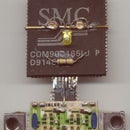
Seal a Microchip TC1047AVNBTR temperature sensor into a plastic tube to make it impervious to water and most other liquids. This is intended for use at low temperatures. The photo shows the completed probe, powered by three AA cells, measuring the ambient temperature as 30.9 degrees celsius.
Step 1: The Sensor
The figure, copied from the data sheet, gives the salient characteristics of the TC1047 temperature sensor manufactured by Microchip. The supply to the sensor can range from 2.7 to 5.5 volts and it converts the temperature to a proportional voltage with a fixed offset of 500 millivolts.
Thus this sensor is ideal for measurement where the result is to be interpreted by a human. A multimeter in it volts range will show the temperature with an offset of fifty. Zero degrees Celsius will result in 500 mV. 100 degrees Celsius will result in 1.5 volts.
Since I was making this to investigate the temperatures in and around a refrigerator, in order to troubleshoot the making of ice cream, I decided to encapsulate the sensor in plastic, it being easier to manage than metal.
The downside is that it might not resist heat very well, as the plastic tube becomes soft if immersed in boiling water. The plastic does not conduct heat very well and so the sensor takes some time to respond to the applied temperature.
If the above points are important to you, there is another instructable on the same subject: https://www.instructables.com/id/Waterproof-a-LM35-Temperature-Sensor/
Step 2: Gather Materials
An exhausted ball pen refill has the sort of plastic tube suitable for housing the probe. Try and find one which has a clean look as the remnants of ink inside can be difficult to clean properly.
Microchip have a very generous policy towards hobbyists and they send you samples of anything they make just for the asking.
Step 3: Solder Wires
I used thin enamelled copper wires to solder to the three leads of the sensor. Although they look like copper, those three wires have a thin coating of enamel which prevents short circuits when they touch each other.
The writing tip was removed from the refill and the tube washed out with some solvent.
Step 4: Enlarge the End of the Tube
Although the SOT23 package of the sensor is one of the smallest, the tube was too small to house it. So its end was made a little larger by forcing an awl into it. You might try a nail, too.
Step 5: Warning!
I found that heating the awl made this part of the job easier. The business end of the awl was made hot by holding it in the flame of a cigarette lighter and then it was pushed into the tube, enlarging it in the process.
WARNING!!
Fire is hot. It will burn you. The awl is a sharp instrument, and if you poke yourself with it might hurt you. If you heat it and poke yourself in the eye with it you will lose the vision in that eye.
So, regardless of what they say over there at MAKE, do not do any of those things. Stay safe.
Step 6: Thread Wires Through Tube
Insert the wires soldered to the sensor through the enlarged end of the tube and pull them out through the other end. The sensor should, when you pull on the wires, be drawn into the flared end of the tube.
Identify the wires at the other end and label them now, because, once the sensor is fixed inside, it is virtually impossible to tell them apart. It would be a good idea to measure and make sure no short circuits exist.
Using the diode check range of the multimeter, the three leads will either show 'open' or as a diode. A reading of zero ohms should be cause for consternation.
Step 7: Seal It In
Holding the end of the plastic tube above the flame of the lighter for a few seconds will cause the plastic to melt. I used a pair of forceps to squash the molten plastic around the sensor, thus embedding it in the tube.
Overheating the sensor might cause it to be destroyed, so it might be a good idea to check its functioning after this step.
Step 8: Extend Wires From the Other End
At the other end of the tube, I soldered the enamelled wires to three wires peeled off a flat cable, insulated the joins using hot melt glue and applied a length of heat shrink tubing over it for mechanical strength.
Paper clips bent into a "V" make great plugs to go into the sockets of a multimeter. Three AA cells in a four cell holder were used to power this sensor.
Step 9: Calibration
There is nothing to calibrate, as microchip have already done that at the factory.
Immersing the sensor in a mixture of crushed ice and water gives an output of 500 millivolts, thus proving that my meter is accurate. Actually, the reading fluctuates a bit, this exact zero reading needs a bit of work with crushing ice and stirring it up to get to.
For occasional use, this sort of jury-rigged arrangement can be made to work. For a more professional instrument, an auxiliary circuit to subtract the .5 Volt offset could be incorporated, thus enabling the meter to show the temperature in degrees Celsius directly.
But that will be another project, all by itself.
Have Fun.


