

Introduction: Weather Station 5


So, this Lazy Old Geek (L.O.G.) built a Weather station over several Instructables.
https://www.instructables.com/id/Arduino-Wind-Chill-Machine/
https://www.instructables.com/id/Arduino-Weather-Station-Part2/
https://www.instructables.com/id/Arduino-Weather-Station-Part3-Rain/
After several years, it stopped working. The main problem was that I had it connected with some Ethernet 5 cable that was not weatherproof and it finally fell apart.
So I decided to build another one. Criteria:
Temperature, Relative Humidity
Barometric pressure
Wind direction, speed and gust
Rain accumulation
Instead of being tethered, it would be battery powered. The batteries would be charged by solar panels and it would transmit data wirelessly to a receiver in my house.
Step 1: Weather PCB (Weather5Xmitter) Design


POWER:
Battery powered: 1 or 2 18650 batteries
Fully charged 4.2Vdc
Arduino: Pro Mini 3.3V 8MHz
Power Requirements:
DHT22 3.3V-6V Temperature – RH
BMP180 1.8V-6V Barometric pressure
nrf24LO1 1.9V-3.6V wireless transceiver
U1881 3.5V-20V Hall effect for rain gauge and wind speed
HMC5883L 3.3V-5V magnetometer for wind direction
PROBLEM: So some of the 18650 batteries come with a flat top. I bought a few of them, They worked fine in my charger but I had some difficulties in some of my adapters.
SOLUTION: I saw this idea on the Internet, don’t remember where. I bought some 5mm x1mm magnets and stuck them on the flat top. Worked great. See pictures.
PROBLEM: I tested the U1881 devices I bought. They only worked down to 3.7Vdc instead of the rated 3.5Vdc.
SOLUTION: I connected the U1881s directly to the batteries and will monitor the battery voltages
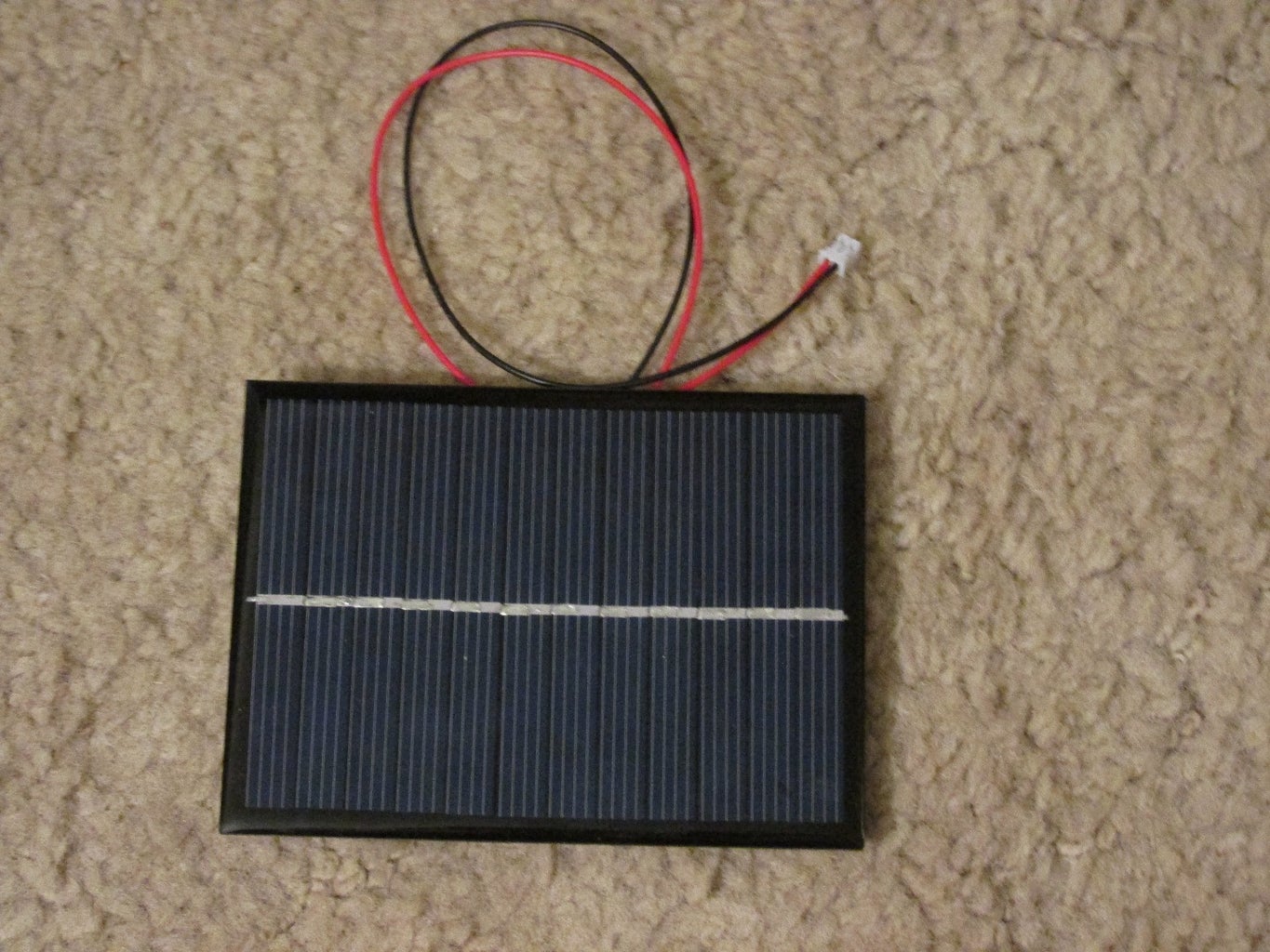
Solar panels: I bought some 6V 200mA solar panels. (Currently using one)
This is connected to a USB lithium battery charger:
The output is connected directly to the 18650 batteries.
Technobabble: The 18650s do not need to be fully discharged and should be able to be recharged while powering the PCB.
I did a quick check with no light on the solar panel-charger and the 18650 connected, there was no current going to the charger. So at night the solar panel-charger will not drain the battery.
Changed temp sensor to DHT22, for temperature and RH.
Added BMP180, pressure sensor for barometric pressure.
The second PCB is Weather5Receiver PCB. Right now, I am using the Receiver PCB from this Instructable:
https://www.instructables.com/id/LOG-Wireless-Temperature-Monitoring/
This PCB has an LCD5110 display but my Sketch isn’t really using this. Since I am OLD, this display won’t work for my needs. I’m looking for a bigger display or will probably just use the serial output to connect with a computer and have a weather station display.
Schematic is attached.
I have attached the Eagle Cadsoft files
Full Disclosure: The PCB I’m currently using is actually an earlier version that I modified as I needed to make changes.
Attachments

Step 2: Hardware


I re-used some of the hardware from my other Weather station:
Wind speed cups: changed hall effect to US1881 (see pictures)
Wind direction: See next Step
Rain gauge: changed hall effect to US1881. I had to replace the base as the cashew nut case lid was crumbling. I used an CD disk. Earlier, I had replaced the funnel as (I believe) the old one was damaged.
Enclosure: I made an enclosure with some vent covers and wood to keep direct sun and rain off of the PCB and batteries.
Originally, I had metal vent plates on all four sides of the enclosure but then I remember that I had to transmit data to the house so I replaced one vent with a piece of plastic and attached the PCB to it. See picture.
Step 3: Wind Direction


Originally, I was going to use the 360 degree potentiometer that I used in the previous Weather Station. However, I noticed that it was a little sticky and took a lot of wind to move it. So I decided to redesign it.
I decided to use an HMC5883L magnetometer. My theory was that if a magnet was rotated above (or below) the magnetometer, it should show the direction of the magnet and thus the wind direction.
The first picture is the HMC5883L magnetometer. Next I attached it to a piece of plastic that fits inside a ½” PVC pipe. I soldered some long wires to the magnetometer.
PROBLEM: How to get the magnet to indicate direction with the HMC5883L.
SOLUTION: Well, I started off with a 3X8 mm neodymium magnet. I had to set the HMC5883L gain to minimum. But it was still erratic. Well, after some experimentation, I noticed that it seemed to work if I moved the magnet about 5 inches from the magnetometer. Finally I decided to use a much smaller 1x5 mm neodymium magnet. That seemed to work at about ½” separation.
Next I glued a piece of plastic to a 5/16” bolt and glued a 1x5mm magnet on its edge to the plastic.
Next I press fit a bearing, same as with the old anemometer into a ½” T.
Next the bolt is dropped into the T and attached with two bolts (not shown).Then the PVC with the magnetometer is inserted into the side of the T.
The next picture shows the magnetometer inside the T above the magnet.
The old weather vane is attached to the bolt.
A short piece of PVC connects the anemometer to the Wind direction.
I used sheet metal screws to lock the PVC pieces so it’s easier to change out parts.
Step 4: Solar Panel


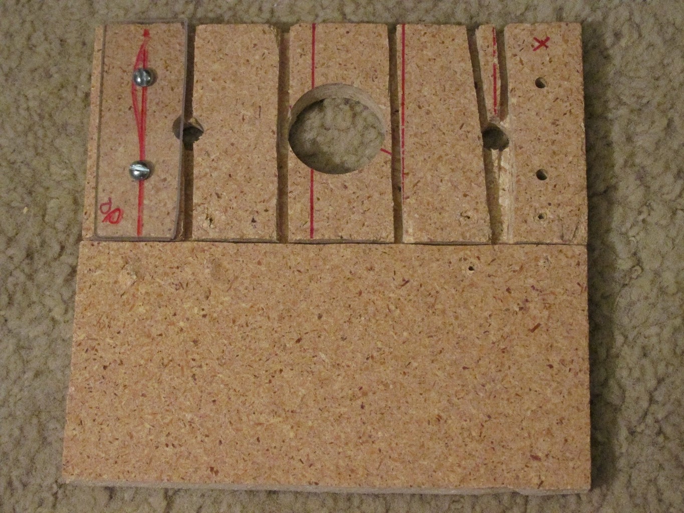


I attached the lithium charger PCB to the back of the solar panel (see pictures)
I took some particle board and cut some slots for water drainage and some holes in it for the support of the solar panel. (Yes, I know my carpentry skills are horrible). Then I chamfered two pieces of plastic to attached the solar panel. The base was attached with two hinges so I could adjust the angle.
NOTE: I didn’t use the baseboard in the picture. The hinges were attached to the top of the enclosure.
So how did I set the tilt angle? Well, I mostly used these websites:
http://www.solarpaneltilt.com/
http://www.solarpoweristhefuture.com/how-to-figure-correct-angle-for-solar-panels.shtml
My thoughts were that for my location, winter is more important as it’s cloudier and colder so for now I set the tilt angle at about 55 degrees.
Step 5: Assembly


Well, I usually design on the fly. The enclosure was designed to use some heater vents to ventilate the box. Originally, they had three louver sections but I cut it down to two and was going to use the third sections for the ends. But as I thought about it, I was worried that they would block the nrf24L01 signal so on one end piece (pointing towards my house) I used a piece of plastic and also attached my PCB to it. The nrf24L01 antenna is actually sticking out below the enclosure.
The wind anemometer and weather vane tied together with PVC and PVC was used for the main support.
I drilled holes thru the enclosure, the PVC and the rain collector so that it can all be mounted with a couple of bolts. This was tricky to attach as the funnel was already attached.
The tipping buckets are on a CD. I attached it to the cashew nut container with some metal strapping. This was also difficult. I put nuts and bolts on the case and CD so they were sticking out and then put the straps onto the bolts with another nut.
I attached two 18650 battery holders wired in parallel inside the enclosure. The sensor wires go into the open bottom of the enclosure.
Step 6: Arduino Sketches

There are two sketches, one for the PCB mounted in the enclosure called Weather5.ino. And one for the PCB in my house called W5Receive.ino
nrf24L01
This is an updated version of maniacBug library
https://arduino-info.wikispaces.com/Nrf24L01-2.4GHz-HowTo
https://github.com/TMRh20/RF24
The network library is in the attached zip file
RF24Network-Development.zip
PROBLEM/SOLUTION: I was hoping to send all of the data at once but I had problems so I divided it into two packages:
struct payload_t1
{
unsigned long counter; // 4 bytes
double TempC; // 4 bytes
double RH; // 4 bytes
double Vcc; // 4 bytes
double BP; // 4 bytes
} payload1;
struct payload_t2
{
double RainAccum; // 4 bytes
double MPH; // 4 bytes
double GustMPH; // 4 bytes
double WDIR; // 4 bytes
} payload2;
This works better.
BMP180
I used Sparkfun sfeBMP180 library.
I used the libraries method of calculating Barometric Pressure
These requires Altitude in meters. I used:
#define ALTITUDE 1417.0 // Altitude meters
DHT22
I used this library:
https://github.com/markruys/arduino-DHT
HMC5883L
I used the Adafruit libraries
https://github.com/adafruit/Adafruit_Sensor
https://github.com/adafruit/Adafruit_HMC5883_Unified
The Weather5 sketch loop is pretty complicating. A simplified explanation:
Wind Speed needs to be monitored continuously. I count the number of revolutions and can calculate RPM. Since this is the same anemometer used in my previous Weather station, I have the adjustment value to convert this to MPH.
Gust speed is calculated by finding the shortest time between revolutions and converting that to MPH.
Rain also needs to be monitored continuously, I just count the number of bucket tips. This is not converted to inches.
The other data doesn’t need to be monitored continuously so it is obtained only before sending packets. This is battery voltage, temperature, RH, BP and Wind direction.
Once a minute, all the data is sent to W5Receive PCB.
W5Receive sketch receives all of the data.
All this does is convert the TempC to TempF and calculated the Wind Chill.
The latest formula, I could find for Wind Chill is this one.
http://usatoday30.usatoday.com/weather/winter/windchill/wind-chill-formulas.htm
All of this data is sent out the serial port.
PROBLEM: I tried this for a few days and found a problem. The batteries were draining too fast.
SOLUTION: I did a quick measure of current consumption. It was about 67mA. I thought this was a little high. I was pretty sure the biggest drain was the nrf24L01 so I did some research and figured out how to power it down after packets sent and powering it up only right before sending packets. This reduced current to about 6mA. Hopefully, this will be enough.
Sketches are attached.
Step 7: Visual Studio Express Program


Visual Studio Express is a free version of Microsoft Visual Studio.
The version I used is Visual Studio Express 2013 for Windows Development.
WARNING: This is a powerful program with lots of features but also pretty complex. I used to be pretty good at using this but alas, I am OLD. I cannot provide any support for this.
I will provide the Project files and tell you how it works. The program is run on the PC with the W5Receive PCB connected to a serial port. The start screen is shown. Select the COM port that the PCB is connected to.
After about a minute, the second screen shot will appear.
Basically, the program reads the serial data coming from the PCB and puts it on the screen. Down at the bottom, the Battery voltage (for the 18650s) is displayed.
Hopefully, the solar panel will keep them charged enough to allow operation through the night.
The Counter will show the number of double packets sent from the Weather station. This should increment every minute and let’s you know it’s still working.
Also the clock at the top will not update until another packet is received.
FUTURE IMPROVEMENTS:
1. Add a Barometer trending indicator to see if BP is rising, steady, falling.
2. A little graphic to indicate Wind direction.
3. Writing the data to a CSV file so can look at historical data.
Attachments
Step 8: Conclusions:


Okay, well it seems to work okay so far.
Concerns: How well the batteries will work.
How PCB holds up in snow, rain, wind.
I actually have an Acu Rite weather station right next to this one so I can do some comparisons.

Participated in the
Full Spectrum Laser Contest 2016


