

Introduction: Wheel Balancer Stand


A motorbike wheel balancer or spoked wheel truing stand built with no welding.
I wanted to build this without welding but still have it adjustable for the initial setting up.
Step 1: Components Laid Out.

- 6 bolts
- 4 brass screws
- 2 pine 38mm square roofing battens
- flat iron base plate 350mmx 50mm x 8mm thick
- 2 rectangular tubing 400mm x 37mm x 15mm
- 2 pieces angle iron
- 4 NSK 608z bearings, preferably metal shield low drag type, not the rubber shield
- 4 drilled and tapped metal plates 5mm thick
Step 2: Bearing Mounts


Bearing mounts made from square angle iron, filled flat on their undersides where they will mate with the tubing, makes setting up easier.
These were then heated red hot and dunked in old car engine oil for the carbon looking finish, not terribly weather proof but fine for indoors.
The M8 bolts are a snug fit in the 8mm ID of the bearing.
Step 3: Slotted Uprights

This way of slotting the tubes and adding tapped keepers was just one way of making things adjustable, it went fairly easy with a dremmel motor tool and a cutoff wheel.
If you don't have a tap and die set available, you could also merely drill the upper and lower plates and run threaded rod down inside the tubing, which in hindsight would probably have been easier.
Step 4: Base Plate

I wanted this to be thick to prevent flexing whilst working on a wheel, it would be hard to measure clearance while the rim is pogoing up and down, the plate was drilled and the holes counter sunk for the brass wood screws.
Step 5: The Assembly


First I attach the tubes to the base using a set square and then tighten the bottom allen head bolts.
Next I use a steel rod out of an old scanner, they are polished and have an accurate surface for my purpose of checking the alignment of the top bearing plates.
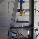
Step 6: In Use

Just to show intended use, naturally I'll need a thicker rod than the scanner rod which was used for setting up, however even in this configuration the heavy side of the wheel soon settles to the bottom.
The addition of 2 centering cones on the scanner rod would make it a viable prospect.

Runner Up in the
Cars & Motorcycles Contest

Participated in the
Bikes and Wheels Contest


