

Introduction: Wifi Relay With ESP8266


This wifi relay can controls any device like lamps or your soldering station with your smartphone or your computer.
Step 1: Materials and Tools


To make this wifi relay you will need:
An Esp8266, which can be program like an arduino and have wifi built in
An USB to TTL converter for programming the esp8266
2 relays 220vac control by 12v
2 transistors TIP122
6 diodes IN4007
A few resistances (2x1k, 2x10k, 330, 220)
Some screw terminal and pin headers
A plug in
2 plugs out
A transformer 12v
A power switch
2 meter of 3 wires cable
A lm317
Capacitors 50v of 1000uf and 10uf
Prototypes pcb
Some screws
For the tools you will need a solder iron, a drill, a 3d printer (optional) and sandpaper.
Step 2: The Relay Board


I divided the electronic in two boards:
- the relay board with the 2 relays and 2 transistors
- the esp8266 board with the module and all the power part (transformer, bridge rectifier and the lm317 for the 3v3 regulate)
This board is very simple, it consists of 2 mosfets how control 2 relays.
I made this board by placing all the components on the Prototype pcb and then I cut the it in the right size with a saw. I solder all the components and after I link them with wire. Pay attention of the diameter of the wire when connecting relay, you should use bigger one for the high voltage.
Step 3: The Main Board


The main board has 3 parts:
-the 12v power which is a bridge rectifier (four diodes) and a capacitor.
-the 3v3 power regulated with the lm317 and the 2 resistors. It creat a constant voltage for the esp8266.
-the module esp8266 with resistors
To make the second board, repeat the same process of the first one. When it's done, check the voltage at the power pin of the module.
Once the 2 boards are done, connect them together wire wire.
Step 4: Make the Box


I made a box with sketchup and 3d print it. If you have access to a 3d printer, download the stl file and print it (20% infill and 0,3mn layers). Sand the box and clean holes. If you don't, you can made a box out of a Tupperware or any plastic box.


Step 5: Finish Everything


You can now finish everything. Place first the electronics and the transformer into the box and glue them. Take the 3 plugs (one in and 2 out), strip the end and connect each wire with the terminals screw by following the schematic. Don't forget to connect the transformer.
Step 6: Program the Esp8266
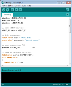

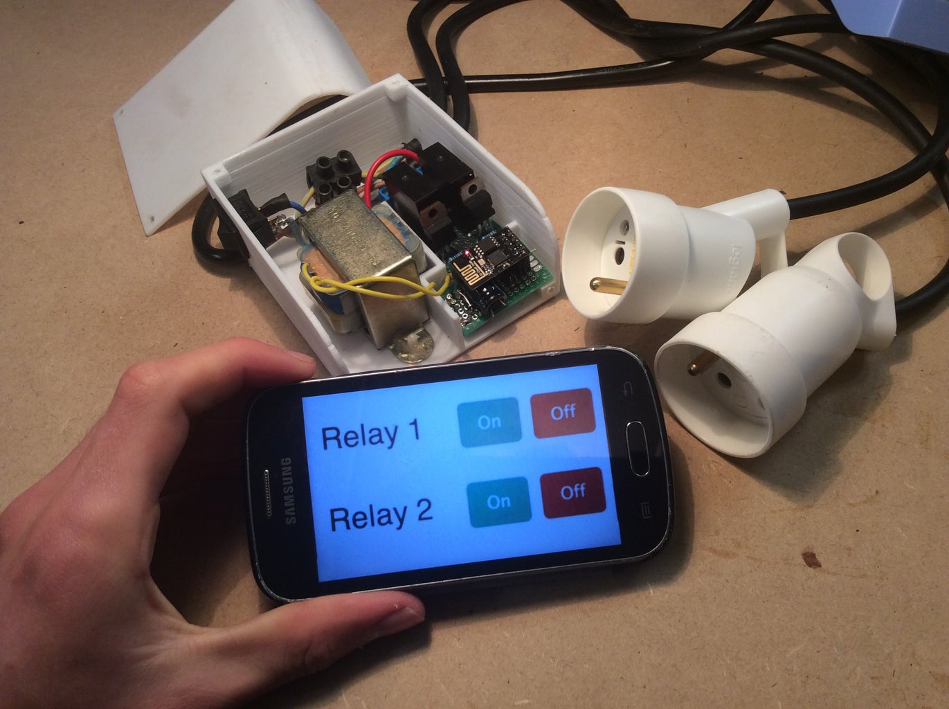
The last step is to program the esp8266 like an arduino. Follow this tutorial if you don't now how to do it: https://learn.adafruit.com/adafruit-huzzah-esp8266-breakout/using-arduino-ide Download my program and upload it into the module. Don't forget to change the wifi name and the password. Enter the IP of the module into any web browser and you will see 2 on/off virtuals switches. This switches control the 2 gpio pins connected to the transistors.
After plug in the module, close the box witch 4 screws. And that's it you can now control any device with your smartphone or PC.
Attachments


Runner Up in the
3D Printing Contest 2016

Participated in the
Home Hacks Challenge


