

Introduction: Wireless Arduino Light-Matching LED Lamp Using Photoresistor


This instructable details the steps necessary to construct a rudimentary wireless light-sensing LED lamp using Arduino Unos and a photoresistor. A possible application for this device would be lighting a room that doesn't have windows with artificial sunlight, matching the actual lighting conditions outside in real time. Let's get started!
Supply List:
Arduino Uno x2
NRF24L01 Wireless transceiver x2 (Optional - NRF24L01 backpack x2)
TIP120 darlington transistor
Photoresistor
5mm LEDs x3
Pushbutton
100 ohm resistor x3
10k ohm resistor x3
Various Jumper Wires
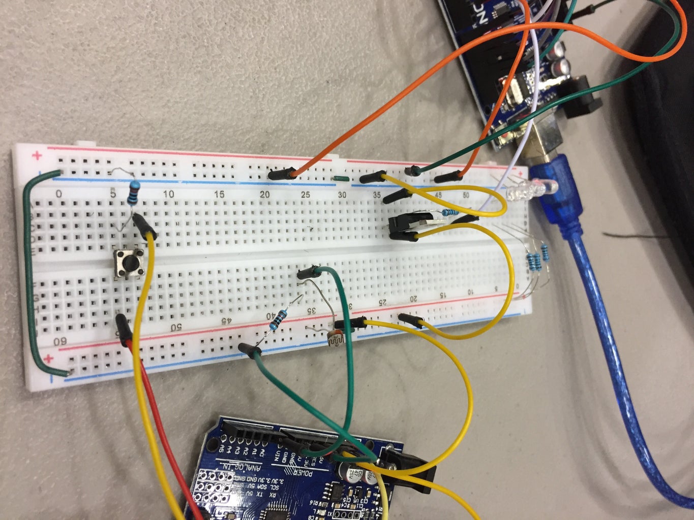
Step 1: Wiring the NRF24L01 Modules and Circuit


In this project, one Arduino will act as a transmitter, sending light level data from the photoresistor when the pushbutton is pressed. The other Arduino will serve as a receiver, taking that data and transforming it into the signal to the LEDs. The first image shows the transmitter diagram, and the second shows the receiver.
Note: in the photos of my project, you'll notice the NRF24L01 transceivers are attached to another PCB. This is a backpack module for the transceivers, which acts as a power regulator. In addition to making wiring easier, these backpacks regulate the power input for the NRF24L01, allowing the use of a 5V power supply. I have omitted these backpacks in my diagram for the sake of clarity.
(If you do decide to use the backpacks, please refer to this link for a diagram of the pin locations in reference to the stock NRF24L01).
Attached below is a PDF copy of the circuit, for easier zooming/detailed viewing.
Attachments

Step 2: Coding the Transmitter
The last step is coding. You'll need to install the RadioHead library or an equivalent library for use with the NRF24L01 modules.
For this project, the transmitter and receiver Arduinos use different code on each. Here is the code for the transmitter:
I have also attached the .ino file (NRF_Send) for convenience.
#include <SPI.h> #include <RH_NRF24.h>RH_NRF24 nrf24; //Initializing a transceiver as nrf24
int button = 5; //Setting pin values for the button and photoresistor int pResistor = A0; int value = 0; //Value of light from 0-1023
void setup() { Serial.begin(9600); pinMode(button, INPUT); pinMode(pResistor, INPUT); if (!nrf24.init()) //Alerts the user if the initialization of the module fails Serial.println("init failed"); // Defaults after init are 2.402 GHz (channel 2), 2Mbps, 0dBm if (!nrf24.setChannel(1)) Serial.println("setChannel failed"); if (!nrf24.setRF(RH_NRF24::DataRate2Mbps, RH_NRF24::TransmitPower0dBm)) Serial.println("setRF failed"); }
void loop() { if (digitalRead(button)) { //Send a message if the button is pressed value = analogRead(pResistor); //Read the value of the photoresistor (0-1023) uint8_t data[] = {value}; //Sets an array called "data[]" containing the light value nrf24.send(data, sizeof(data)); //Send the array to the receiever nrf24.waitPacketSent(); //Wait until the packet has been sent Serial.println("Light Value: " +String(value)); //Print the light value into the serial monitor } }
Attachments

Step 3: Coding the Receiver
For the receiver, the code also uses the RadioHead Library.#include <SPI.h>
#include <RH_NRF24.h>
RH_NRF24 nrf24;
int LEDPin = 3; int value = 0; //Value of light from 0-1023
void setup() { Serial.begin(9600); pinMode(LEDPin, OUTPUT); if (!nrf24.init()) Serial.println("init failed"); // Defaults after init are 2.402 GHz (channel 2), 2Mbps, 0dBm if (!nrf24.setChannel(1)) Serial.println("setChannel failed"); if (!nrf24.setRF(RH_NRF24::DataRate2Mbps, RH_NRF24::TransmitPower0dBm)) Serial.println("setRF failed"); }
void loop() { // Wait for a message uint8_t buf[RH_NRF24_MAX_MESSAGE_LEN]; //Store the received message as an array called "buf[]" uint8_t len = sizeof(buf); //Store the size of buf as "len" while (nrf24.waitAvailableTimeout(200) && nrf24.recv(buf, &len)) //Receives the message for 200 milliseconds or until the whole message is receieved { value = buf[0]; //Sets value to the first index of buf[], which is the int from the photoresistor analogWrite(LEDPin, map(value, 0, 1023, 0, 255)); //Sets the PWM pin to output a scaled value between 0-255 for the LED brightness Serial.println(String(value)); } analogWrite(LEDPin, 0); }
Attachments
Step 4: DONE!
Enjoy playing around with different light levels and watching the LEDs match them! The photoresistor can be finicky sometimes, and works best in a dark room with a localized light source (but can work outside with the sun too).


