

Introduction: Wireless Remote Using 2.4 Ghz NRF24L01 : Simple Tutorial Using of NRF24L01 & Arduino


Hello Everyone this is my second instructable . After lots of surfing on GOOGLE when I wont able to find a easy and a simple tutorial for NRF24L01 transceiver then I decided to publish an instructable on this. This is a simple short and easy tutorial for NRF24L01 Radio 2.4GHz Transmitter Receiver. In this tutorial I am going to control led using a pair of NRF24L01 transceiver.
Step 1: Small Introduction About NRF 24L01 Transceiver
The nRF24L01 is a highly integrated, ultra low power (ULP) 2Mbps RF transceiver IC for the 2.4GHz ISM (Industrial, Scientific and Medical) band. With peak RX/TX currents lower than 14mA, a sub μA power down mode, advanced power management, and a 1.9 to 3.6V supply range, the nRF24L01 provides a true ULP solution enabling months to years of battery lifetime when running on coin cells or AA/AAA batteries .
Step 2: Material Require


- 2 PCS NRF24L01+2.4 GHz Wireless Transceiver module
- 2 Arduino any (I have used one arduino R3 & nano)
- Male to. femal jumpers
- LED
- Any Switch
- 10K resistor
Step 3: Connections


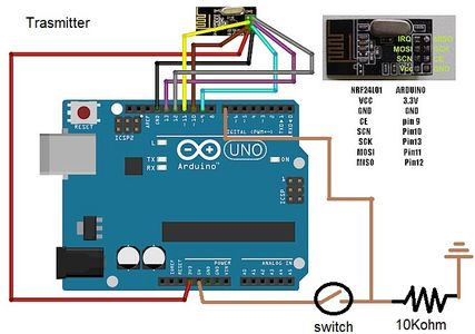
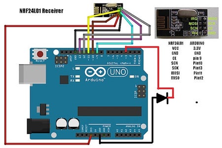
- Connect the following pins to your Arduino:as shown in figure
- Pin 9 - CE
- Pin 10 - CS(N)
- Pin 11 - MOSI
- Pin 12 - MISO
- Pin 13 - SCK
- 3.3v - VCC
- GND - GND
- On the Receiver Pin 3 - LED
- On the Transmitter Pin 7 - Button
- same connection for receiver and transmitter and you can use any arduino board
Step 4: Coding Arduino
For coding arduino first we need some library files so follow the steps given below :
1. Download the ZIP file (library file zip folder from attachments ).
3. Unpack the ZIP file.
4. Go to arduino library folder
5. And paste both the folders named " nFR24L01" and "RF24" into it.
Now, program the Arduino receiver and transmitter
Code for Receiver
<p>#include <SPI.h><br>#include "nRF24L01.h"
#include "RF24.h"
int msg[1];
RF24 radio(9,10);
const uint64_t pipe = 0xE8E8F0F0E1LL;
int LED1 = 3;</p><p>void setup(void){
 Serial.begin(9600);
 radio.begin();
 radio.openReadingPipe(1,pipe);
 radio.startListening();
 pinMode(LED1, OUTPUT);}</p><p>void loop(void){
 if (radio.available()){
   bool done = false;
   while (!done){
     done = radio.read(msg, 1);
     Serial.println(msg[0]);
     if (msg[0] == 111){delay(10);digitalWrite(LED1, HIGH);}
     else {digitalWrite(LED1, LOW);}
     delay(10);}}
 else{Serial.println("No radio available");}}</p>
Code for Transmitter
<p>#include  <SPI.h><br>#include "nRF24L01.h"
#include "RF24.h"
int msg[1];
RF24 radio(9,10);
const uint64_t pipe = 0xE8E8F0F0E1LL;
int SW1 = 7;</p><p>void setup(void){
 Serial.begin(9600);
 radio.begin();
 radio.openWritingPipe(pipe);}</p><p>void loop(void){
 if (digitalRead(SW1) == HIGH){
 msg[0] = 111;
 radio.write(msg, 1);}}</p>
Attachments

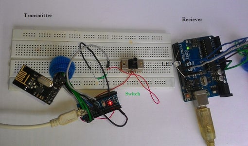
Step 5: Testing
This is a last step after completing the circuit and coding part we can easily test it by switching "ON" and "OFF". .
When switch is "ON" on transmitter side connected to pin 7 of arduino then led glows on receivers side connected to pin 3 of arduino .Video Shows the output of this project.


