

Introduction: Work Coordinate System

More by the author:


About: Autodesk Technology Center San Francisco is a hub for research, development, and demonstration of new manufacturing technologies and workflows relating to configurable microfactories.

Setting up the Work Coordinate System
In your CAM program, you selected a corner of your stock as the WCS. The G-code for the WCS is G54.
- These steps will use the probe to find exactly where that point is.
Prepare your stock
In your CAM software, you entered the approximate size of the stock. You'll need to cut the stock, then measure the actual size and update your CAM program.
- Cut your stock to the dimensions listed on your setup sheet.
- Measure the stock with calipers.
- Update your setup(s) with your actual measurements.
- Regenerate your toolpaths.
- Generate your Setup Sheets.
- Secure the stock in the mill.
- Elevate your part with parallels to avoid machining the vise.
- Use rubber mallet to seat the part firmly on the parallels.
- Minimum clamp distance is 1/8".
- Measure the part stickout with calipers.
- Compare this to the minimum part stickout you calculated in your Setup Sheets.
Finding Z
- Perform a tool change to put the probe (#100) in the spindle.
- See the first two instructions on page 14.
- Jog the tip of the probe to 1/4" above the top of your stock.
- Press OFFSET until the Work Zero Offset is highlighted.
- Use the arrow buttons to highlight G54.
- Take a photo, so you can confirm that the values change.
- Cursor to the right until the screen changes to show various work offset probing options.
- You'll start by measuring Z only, on top of your stock.
- Enter 11 and press WRITE/ENTER.
- Navigate right to select the Work Probe Inputs.
- Select the Z distance.
- Enter -0.4 and press WRITE/ENTER.
- This value must be greater than the actual distance.
- Press CYCLE START to run the probe.

Take care while jogging the machine. It's easy to break the probe by moving too fast, too far or in the wrong direction.
- When jogging, you'll need to set the axis (X, Y or Z) and the increment - how far the spindle or table moves for each click of the jog handwheel.
- Press HAND JOG to enter jog mode.
- Press .01 to set the increment (0.01" per click).
- In the Jog keys section, press the axis you want to move.
- Look at the display and check that your desired axis is highlighted in yellow.
- It does not matter if you choose + or - for this axis.
- Rotate the jog handwheel clockwise to move in positive direction and counterclockwise for negative.
Step 1: Finding X and Y


You have set your Z work coordinate; now set X & Y.
- Jog the probe over the back left corner of the stock.
- See image
- Make the Work Zero Offset table the active window.
- Navigate to the Probing Options page.
- You want to probe the back side and left edge of the material.
- Enter 9 and press WRITE/ENTER for Outer Corner.
- Navigate right to edit the Outer Corner value.
- Enter 4 and press WRITE/ENTER.
- This will select the back left corner.
- Enter -0.4 and press WRITE/ENTER for incremental Z, X & Y.
- PRESS CYCLE START.
- Check that the full diameter of the probe contacts the material. (see image)
- Navigate left and check that the G54 coordinates have changed. Compare them to your photo.
- Look at the WCS on your setup sheet and make sure it matches the WCS in the mill.
- A probing cycle is fairly safe. If the probe hits something unexpected, it will instantly stop, except in hand jog mode.
- If there is a problem, the red light on top of the controller will flash and an error will display on screen.
- RESET to clear the error. Change your work probe inputs and try again.
Step 2: Right Hand Rule
To help remember the X, Y & Z axis, you can use the right-hand rule.
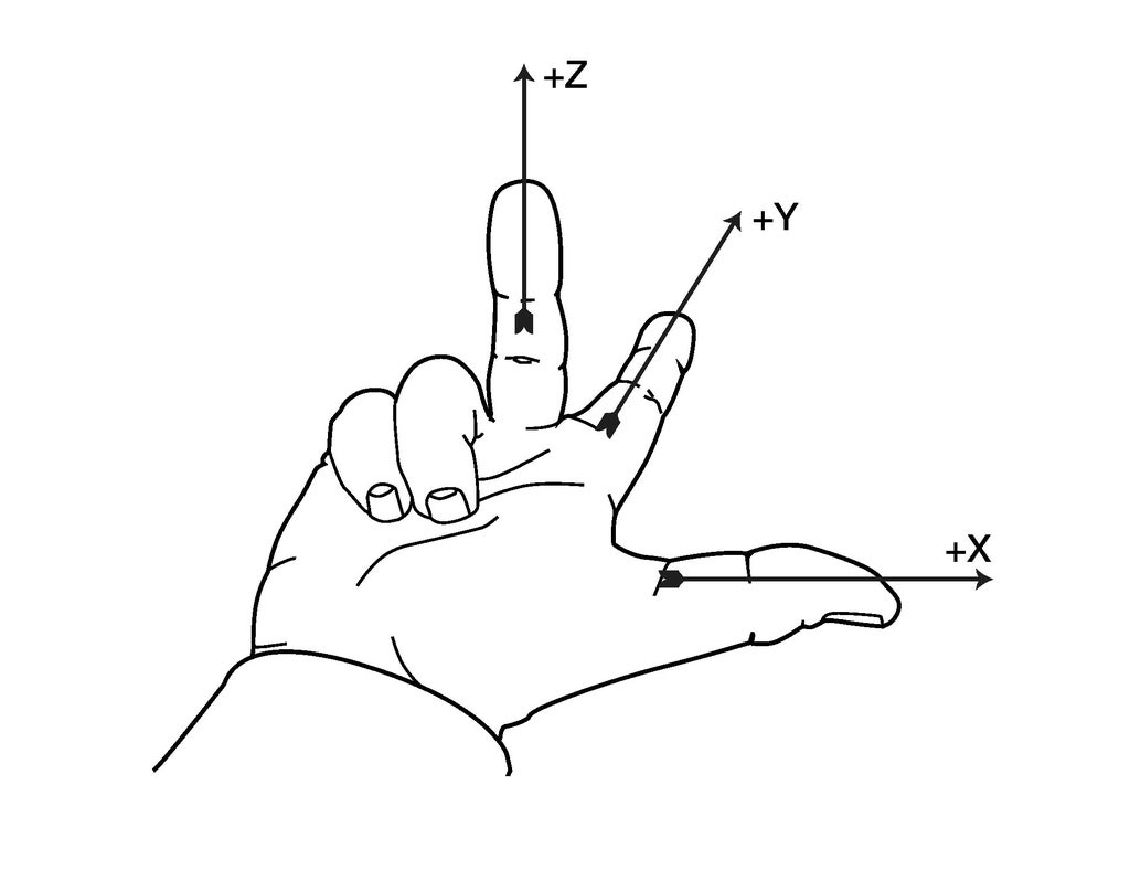
Hold your right hand out, like in the illustration. Each finger points in the positive direction.
- Make sure you know which way you're going to move before operating the probe.
- Turn the handwheel very slowly to start.
- Positive and negative directions are relative to tool motion, not table motion.


