

Introduction: Zoetrope Fidget Spinner


It's already spinning, why not add an animation? Now you can be distracted by a cat video while you get out that nervous energy. It's a simple design: two wheels, two bearings, two caps for your thumb and forefinger, and a drum with slits in it press-fit together.
Step 1: Adam Savage Likes It!
Here's a video of Adam and company talking about it on their podcast, Still Untitled. Scrub to 23:10!
Step 2: Idea

I got this idea from darlingtom's instructable Animated Fidget Spinner. He noticed that the spinning motion opens it up for the possibility of animation. He made a phenakistoscope out of his, which as you can see requires you to look at it in a mirror.
It's a dead-simple, clever design, but I wanted to make something a bit more elegant that wouldn't require a mirror.
Step 3: Design

Although some version of the zoetrope might date back to 1st century BC China or even 3,000 BC Iran, the modern version I based this design on was patented in the US in 1867.
It's basically just a rotating drum with slits cut into it and sequential frames on the inside of the drum below and in line with the slits. This arrangement ensures that the slit is directly in line with the picture, but it also means that the drum has to be tall enough for a slit and a picture stacked on top of each other.
Since this is a fidget spinner and it needs to fit in someone's hand, I made mine so that the slits would be in line with the frames. The frames are then in between the slits, which still works.
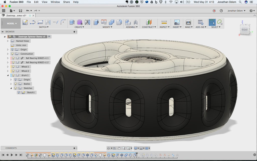
Step 4: 3D Modeling
Believe it or not, this is actually a pretty simple 3D modeling project. All it is is a drum with 12 slots in it evenly spaced, two identical wheels on the top and bottom with holes cut out to let light in, and a couple of caps and bearings. The video above shows the process step-by-step, and I'll elaborate on it below.
Fusion 360 is free for students and hobbyists, and there's a ton of educational support on it. If you want to learn to 3D model the kind of work I do, I think this is the best choice on the market. Click the links below to sign up:

First, I used the Insert McMaster-Carr Component feature and brought in a couple of bearings. In this example, I used 608ZZ bearings- common bearings for fidget spinners.

I placed the bearings so that there would be enough of a gap between them to be able to see through to the animation frames- about 11mm.

I drew a profile of the top wheel and the drum in one sketch. On the right, you can see a stepped press-fit feature. I only needed half of the profile because I was planning on making the 3D parts using Revolve.

Using Revolve, I made a disc that would serve as the base for the wheels.

I made another sketch with lines patterned around the center at 120º, then offset two of those lines to make a profile that I could use as a void that would leave spokes with enough width to hold together.

I used the Extrude command to make the void.

I filleted the inside edges of the void to give the spokes a smoother transition.

I used the Modify>Pattern>Circular Pattern tool to make 3 evenly spaced voids out of the faces I just made.

I filleted the edges of the wheel to make it smoother to the touch (and to the eye) and made a copy for the bottom wheel.Using the original profile I drew, I

Using the first profile I drew, I used Revolve again to make the basic shape of the drum.

I made a new sketch for the slot shape that I would later need to cut out.

I used Extrude to make a new body that extended past the boundary of the drum shape.

I used the Pattern tool again to make 12 equally spaced bodies that I could use to cut out of the drum shape.

Using Modify > Combine, I cut the pill shapes out of the drum.
I used the Chamfer tool and Fillet tool to make raked profiles around the slots. I figured this might make the animation easier to see and it has the added bonus of using less filament.

I drew a new profile for the cap piece. The Intersect tool in the Sketch menu is helpful in ensuring that the parts will fit properly.

Using Revolve again, I made the cap.

I made a revolute joint to test out the motion with the animation frames, which I'll get to in the next step.
Step 5: 2D Design

To get an exact layout for the animation frames, I had to do a little math. I can easily measure angles and radii in Fusion, but I don't know an easy way to get the circumference or arc length of a curve. Not to worry, the math is simple and the internet has no shortage of ready-made calculators.
The radius of the inside of the drum is 38.5mm, which gives me a circumference of about 241.9mm. The height of the inside face is 11.3mm, so I start with a rectangle with those dimensions.
The angle between the edges of the slot is 4.5º, so I get an arc length of about 2.9mm there. The slot is a pill shape that's 2.9mm X 9.3mm.
That gives me a rectangular frame area of about 17.1mm X 11.3mm.

I did all the layout work in illustrator because it's easy to distribute shapes there, and you can print from it directly with a vinyl cutter.
The finished layout is a tape with slots distributed evenly in the middle, and half slot shapes on the outside edges.
Step 6: Making the Animation Frames

I made a few different versions of animations to try out with the spinner. This one is a motion study of a cat done by Eadweard Muybridge in the 19th century. He pioneered the motion picture way before anyone else was thinking this way, and he's got lots of public domain photo sequences that make great animated images.

I saved each frame individually, brought the frames into illustrator, then placed them in the proper locations between the slots.


Here's another one by Muybridge.


This is a wheel I did myself.


This is a kind of Op Art animation using ellipses.
Step 7: Testing Animation in Fusion
Since Fusion allows you to animate joints live in the modeling environment, I figured I might as well test out the animations virtually before I started printing the parts. The video above shows how I did it.
Basically, I just took a JPG of the cropped animation ribbon, then applied that to a material in Fusion that I placed on the inside face of the drum.
When I select "animate model" under the rotational joint in the browser, the drum rotates and I'm able to get a rough idea of how the animation will look.
Step 8: Printing and Assembly
There's nothing to this part. I just made STLs from Fusion, brought those into Simplify 3D, and printed them out on the Makerbot. If you don't know how to do this, I'd suggest taking my Beginner 3D Printing Class.

Everything is press-fit together, and with the right tolerances it's easy to disassemble if I want to change out the frames.
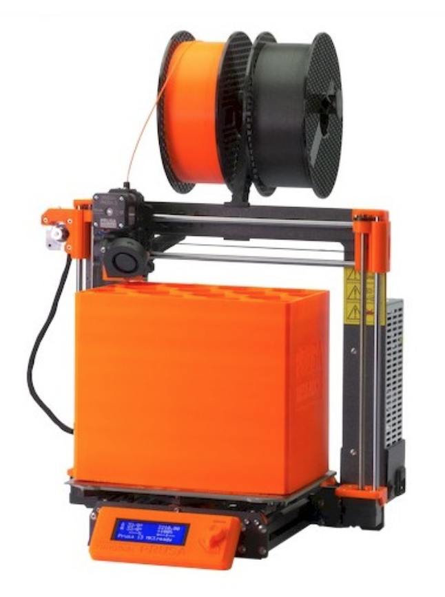
I use a Prusa I3Mk3S for just about everything. It's the best bang for your buck, in my opinion- very well made, 3D printable replacement parts, accurate and reliable.
Step 9: Lessons Learned


The skateboard bearings are too sticky to really get a good spin, so I redesigned it with another set of bearings that are flanged and double shielded with an ABEC-5 rating. With these bearings it spins for about 40 seconds (although at that speed the cat is running really fast!).
Want one? Click here and I'll make one and ship it to you.
Step 10: Print Your Own
If you want to make your own, I've attached STL files here of a simpler version. Enjoy and please post an IMadeIt!
Bearing: 608ZZ on Amazon


