

Introduction: Babbletron - an Interactive Exploration of Computer Generated Speech


The babbletron is a device that lets you explore the world of computer generated speech. The basic concept used by the babbletron is that synthetic speech can be approximated using a small set of phonetically isolated speech fragments, called phonemes. To produce a word or phrase, you combine phonemes in a sequence that makes a voice recognizable to the human ear.
This method of speech generation has been around for at least two decades, and is an efficient and compact means of representation, but does require some processing power. The fairly recent introduction of low cost programmable micro-controllers has reduced the cost of speech synthesis hardware down to the price where makers and hobbyists can incorporate synthetic speech in their own projects and prototypes.
The babbletron is a sandbox of sorts that can serve to explore computer generated speech using low cost hardware, and easily understood software. This instructable can be used as a starting point for exploring your own artificial voice projects, and give you some general tips on how to construct a demonstrable project for public consumption.
Step 1: Parts


Arduino UNO compatible microcontroller
Ginsing waveform synthesizer shield
LinkSprite LED matrix shield
Custom 64 input mux shield
I/O panel and cabinet
Suppliers
GinSing ( www.ginsingsound.com ) GinSing waveform synthesis shield w/ Babblebot IC
LinkSprite ( www.linksprite.com ) 8x8 LED Matrix kit
Home Depot ( www.homedepot.com ) 4'x4' Sande plywood, 6'x2"x2" stud, misclleanous hardware
OfficeMax ( www.officemax.com ) 24"x36" print and lamination services
Digikey ( www.digikey.com ) HEF4015B IC, 16 pin DIP sockets, wire, DB23 connectors, jacks
Step 2: Prototype Hardware


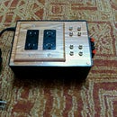
Contrary to the image presented by the large button panel, the babblebot is actually a small device. If you are considering using voice synthesis in your project but don't need a big user interface, you should consider wiring up a small breadboard concept first. Even if you are going to do a big build, you should still probably start with a breadboard design.
Pictured here is the babblebot sans the button panel, which is great for testing functionality. By stacking the Arduino, the GinSing shield, Sparkkun protoshield (with breadboard), and the LED matrix we have the basic electronics to implement the babbletron. Also pictured here is a potentiometer used to simulate the footswitch used in the final design to control voice pitch.
Since the shields all pass the Ardiuno pins, the only real work in building the prototype is to seat the LED shield and connect it (via jumpers preferably) to the pins. To connect the LED matrix display, wire shield D8 to display DIN, D9 to display CS, D10 to display CLK, 5V to display VCC, and GND to display GND as shown. The only other connections in the prototype are a potentiometer on the [ PWR, GND, A1 ] Arduino pins, and either a speaker or 1/8" stereo jack to amplifier.
Step 3: Prototype Software

The following discussion assumes that you are familiar enough with the Arduino to load and execute code on the device using the standard IDE. If you are new to Arduino, please refer to the "Getting Started" section on the Arduino website ( www.arduino.cc ).
1. Open up the IDE, and select the board and communication line associated with the Arduino. To verify you can try the sample "blink" program; if this works you are ready to load the babbletron code.
2.Download the Zip file from this page and uncompress it ( usually be double clicking it ). This will create a folder in your download directory that you can either run directly ( by double-clicking the "babbletron12.ino" file ) or copy into your Arduino sketchbook folder if you wish it to show up on your menu.
3.Perform the build and run operation ( the arrow button in the IDE ). When the program starts, the display will flash briefly, and then you will hear "I am babbletron" audio output with an accompanying facial animation as seen in the video.
Note: This code base is built to accommodate the 64 button mux board, so if you are not planning on using the buttons you can remove this function by deleting the C_Mux tab, and then deleting the few references to the "buts" class in Z_Main. This will also free up digital inputs D5,D6,D7, D11, D12, and D13 for other uses as you see fit.
Attachments

Step 4: Enclosure


Building the enclosure involves several steps that for convenience are presented on a single page here. As you may choose to build a different style of cabinet use this step as a guideline. Take time following these steps; no significant skills are required other than some patience and a somewhat steady hand. If you are new to this process, its best to practice on scrap material to make sure you understand what is required and what the outcome will be.
1.Design the panel decal. Included on this page is a PDF file that matches the control panel layout you see here, although you will most likely want to design your own. This file was created using Open Office and exported as a PDF, but you can use whatever drawing program you feel comfortable with. Once the PDF file is created, you can take the file to a local printer ( i.e. OfficeMax ) and have it printed on a large format printer and laminated. This results in a waterproof surface that is ideal for mounting on the plywood backing.
2.Cut the panel pieces. Lay out the panel on the plywood and measure the panel size against the decal. Use the remaining plywood to create side panel pieces. As you can see in the picture, the sides can be cut from the same piece and measured to create the tilt as desired.
3.Mark hole locations. Cut out any opening (such as the display window used here) and mark drill locations. To do this, tape the decal to the panel, and use a craft knife and small pilot bit to avoid tearing or wrinkling the decal. Once the locations are marked remove the decal and put aside for later.
4.Cut the panels. Using a jig saw and a drill, cut out any non-drill openings by drilling into the corners and then squaring off using the saw a pictured. Using the pilot holes from the last step, drill the button holes. This project uses large arcade buttons, so a spade bit was required; if you use a spade bit be sure to go easy on the wood so as not to rip parts off the back of the panel.
5.Assemble and add bracing. Secure the front panel to the side panels by pre-drilling holes in the font panel that line up with the side panels using a bit slightly smaller than the screw you are using. Finish the hole with a counter sinking bit so the screws will sit flush, and then screw the pieces together. Carefully turn over the enclosure and measure, cut, and screw the bracing pieces from the 2x2 stud piece. Use the same screwing technique to attach and sink the screws.
6.Sand and paint. Fill the screw holes with wood filler, and sand the outside surfaces of thenenclosure with 150 grit sandpaper. Inspect and clean any drill holes or openings that may have defects on the back side of the panel to ensure the buttons will go in easy and flush. Paint with spray paint to a clean finish, about 3 coats.
7.Apply the decal. Carefully cut out two button holes with an craft knife on the template on opposite corners using a button nut as a guide; this will allow you to align the decal with the holes. Mask off the panel from the rest of the enclosure and apply a light coat of spray adhesive glue as per the directions on the product. Align the decal using the guide holes and press and let dry.
8.Mount buttons. Using the craft knife trace the outline of the holes by running the knife around the drilled openings and remove the material; with practice this will take only a few minutes. Mount the buttons on the panel first loosely until all are mounted, then orient the button solder tabs from underneath to all point the same direction and tighten. Aligning the tabs will make the next step easier.
Attachments

Step 5: Button Wiring


If you are not using the button panel you can skip this step and replace it with one that is consistent with wiring your own panel interface.
In this design, we use 64 buttons, which allows for all 58 phonemes, 2 inflections, 2 time delays, and 2 record / play buttons. The multiplexer shield can support this many buttons by scanning an 8 x 8 grid comprised of rows and columns and checking the state of the current row and column to form a complete circuit. When a button is pressed, the corresponding row and column for that button will provide a zero volt signal on the mux output; otherwise it will be 5V.
The mux supports 64 buttons in an 8x8 pattern, which at first seems impossible given the layout on the panel, but in reality the physical location of the buttons do not matter - only that each button has its own unique row and column line. Since there are 8 rows and 8 columns, there are a total of 16 lines from the wired panel that will connect to the mux shield.
Wiring the buttons first involves wiring each row to a set of eight buttons each. If the buttons are aligned, you can pick one side of the solder tabs ( i.e. left side ) and wire the first eight buttons in proximity. Likewise, the next row will be tied to the next eight buttons, and so on until all eight rows are wired. This will solder 1/2 of the connections as 8 rows with 8 buttons each. Once the rows are wired, use the same operation for the 8 columns using the same process.
Note that deciding which row and column for any given button becomes hard to figure out when the grid is not regular, but this is easily determined with some debug prints in the code.
Step 6: Breadboard Mux


If you are not using the button panel you can skip this step and replace it with one that is consistent with wiring your own panel interface.
Although in the end the multiplexer (mux) shield will be built permanently, it is a good idea to verify the circuit works by breadboarding it as we did earlier with the rest of the system. To create the mux breadboard, follow these steps:
1.Start with open breadboard shield. If you only have one protoshield, you can remove the breadboard wiring you used when prototyping the display; it should no longer be needed now that you have verified operation.
2.Lay out the ICs. As you can see in the picture, lay out the ICs across the center of the breadboard end to end. This is also how you will arrange the protoshield so it will be easy to transfer. Make sure that both ICs have pin 1 (dot) aligned to the top of the board. From this point on we will refer to the top IC as the "column" IC, and the bottom IC as the "row" IC.
3.Wire the shield power connections ( GND, +5V ). Although not required, using premade jumpers for this operation will make it very easy and ensure solid connections on the shield headers. Both ICs will have pins 6 ,7,8 ( E, VEE, VSS ) wired to ground, and pin 16 ( VDD ) to +5V. Wire the pin 3 Z connections for each IC; the row IC will go to the resistor ( 4.7K ) and then to +5V, and the column IC will go directly to ground. Finally wire from the row IC pin 3 Z to A1 on the shield.
4.Wire the shield address connections ( S1, S2, S3 ). Each chip has 3 lines that control the address that the mux will be inspecting. The Arduino will set these lines for each IC to tell the mux what row/column to pass to the analog line for detection. There are 3 lines since we are using eight possible addresses. On the chip they are pins 9,10, and 11 ( S1 , S2, S3 ). For the row connection connect row IC S1,S2, S3 to pins 11,12, and 13 on the shield respectively. For the column connection connect column IC S1,S2,S3 to pins 5,6, and 7 respectively.
5.Wire the shield sensor connection ( A1 ). When a particular row and column address is selected by the Arduino, the mux will connect that circuit to the Z in/out of the two ICs. By tapping off the Z pin of the row IC, you can sense if that row/column has been connected. To determine this on the Arduino, connect the row IC pin 3 ( Z ) to the shield A1. The code will check for the value of A1 determine if a button was pushed.
6.Wire the button matrix connections. In the picture you can see that an additional breadboard was used to bridge between the panel wires and the breadboard wires; this make its physically easy to connect the two components, but also helps lay out a connector that we will build using a DB25 connector. This is not required, but will make it easier to manage to two components separately. On the row IC, connect the 8 rows lines to pins 1,2,4,5,12,13,14, and 15. Likewise connect the column lines to the same pins on the column IC.
Step 7: Protoshield Mux


If you are not using the button panel you can skip this step and replace it with one that is consistent with wiring your own panel interface.
The Sparkfun Arduino protoshield will be used in this step to harden the mux shield made in the previous step. In addition, we will add a DB25 connector to make it easy to install on the panel, but this is not required. We will start by placing two 16 pin IC sockets on the protoshield slightly offset to allow for more room when adding the panel wires.
If you are new to using a shield like this, the basic idea is to place things to be wired together next to each other, and then create a wire bridge that can be used to flow solder between the two holes on the connection. The first few pictures show in detail how the wires are placed and how they look on the bottom when soldered together. Note that the back of the board does not have any wires; just solder connections as there is no trouble overlaying wires if they are insulated on the top side.
Following the same procedure as was used to wire the breadboard, we will first solder the power lines, then the address lines, then the sensor line, and finally the panel wires. As the last step we wire the jumper headers and filter caps that came with the kit. The other components in the protoshield kit are not used here.
Pictured here is a use of the DB25 connector to allow this shield to break away from the panel for later modifications and repairs if need be. We prefer to use this method also to minimize wire length and complexity during the build.
Step 8: Electronics Package


In this step we will be assembling the electronics package, which consists of the Arduino, the mux shield, the synth shield, and the LED matrix display. The only other electrical connections outside of this package are the front panel buttons and the back panel jacks.
1.Solder LED Matrix lines. As per the earlier schematic, the Arduino pins D8, D9, D10, +5V, and GND will be connected to the LED matrix display. Solder these lines into the protoshield next to the corresponding pins. In the example here, jumper wires were used with one end cut off and soldered to the board to allow removal of the display.
2.Solder pedal lines. If using the pedal potentiomer ( or another sensor ) you will need a +5V, GND, and sensor line ( A1 in this case ) that is best connected to the protoshield; in this way all external wires other than the speaker / line out will be wired into this board. In this example we run these lines out to the DB25 connector so that all external connections are done through one cable bus.
3.Stack shields. Although it does not strictly matter, we suggest a stack that has the Arduino on the bottom, the mux shield in the middle, and the Ginsing board on top; this puts the most separation between the Arduino processor and Ginsing processor and reduces EMI between the boards; it also puts some strain relief on the wires to the console.
4.Load the mux ICs. Now that all soldering is complete on the mux shield, populate the IC sockets and tame the wires down so that the shield is stackable.
5.Build the display panel. Using a small piece of Masonite board, layout and drill holes to mount the stack to the board, and to mount the display. In this case the display is located next to the Ginsing board and slightly above so standoff bolts were used to place the display close to the window opening on the panel.
Step 9: Final Assembly


With the enclosure ready, buttons wired, and electronics package ready, we now simply put the pieces together to complete the project.
1.Wire the panel to the mux shield lines. As per our previous steps you can connect the row/column lines from the panel to the row/column lines on the mux shield. Pictured here is the other side of the DB25 connector attached to the row and column lines that match the connector on the mux shield.
2.Mount electronics package. To mount the display from the bottom, create a window barrier out of masonite and fush mount standoff screws. Attach the barrier to the panel using short hobby wood screws. Using an extra set of nuts, you can set the offset distance between the panel front and the electronics package to ensure an accurate fit.
3.Build and mount jack plate. Using a small piece of masonite cut holes for the audio output jack and the pedal switch (if appliccable). Here we are using a stereo RCA jack to feed an amplifier at line level, and a 1/4 strereo jack wired with +5V, GND, and A0 to match the previous breadbard prototype.
4.Build and mount bezel. Using a small piece of clear plastic or lexan ( we used a colored clipboard at OfficeMax ), score the material to match the size of the bezel to create on both sides and snap off cleanly. Using fine sandpaper or emory board smooth the cuts and slightly round the corners. Attach the bezel using thin two sided tape cut around the overlap between the bezel and the panel.
Step 10: Buld Button Map

To perform this operation, you will first need to find out what button code is generated when each button is pushed. This can be done by adding this line to the loop() code in the Z_Main source file:
// read the button panel for a new input


  int newButton = buts.update();      // this line is already in the file
  Serial.println ( newButton );       // this line has been added to print button value
When the program is run now, you will see the value of the button pressed appear in the display. Using the worksheet included here, you can map the values to the corresponding button on the panel. So for instance in this wiring example when the "a" button was pressed on the panel the printout read "3". Do this for every button, noting that if the wiring is correct each button will have its own unique value from 1 to the number of buttons you have.
The final step in setting up the mapping is to modify the table labeled but2Allophone[] in the Z_Main source file. The current file looks like this:
 byte but2Allophone[] = {  _HO , _DE , _IE , _A , _I , _DO , _HE , _AA , _PE , _R ,
                           _TS , _UE , _OR , _U , _PO , _V , _AIR , _BO , _AE , _OB ,
                           _AU , _EB , _BE , _CH , _SE , _SH , PLY , _TH , REC , _T ,
                           _SO , _THH , _E , _ER , _ED , _GE , _OD , _F , _EE , _GO ,
                           _OI , _OU , _OE , _M , _LE , _LO , _OO , _NE , _NO , _KE ,
                           _NGO , _EK , _NGE , _KO , _J , _OK , _Z , _PITCHUP , _W , _PA1 ,
                           _Y , _PITCHDN , _ZH , _FD2 };
This table maps the button value to the phoneme to be played. For example, the first item in this table is _HO, which maps to the zeroth button in the button table as per the chart. To rebuild this table, start with an empty array, and go one be one by button value and enter the corresponding phoneme into the array.
Attachments
Step 11: Congratulations!

If you have made it this far in the instructable, you are to be commended on creating a great sounding and great looking project to amaze your friends and confound your enemies. It is also possible that you just skipped to the end to find out more or ask questions.
In the case of the former, your reward comes from a job well done, in the case of the latter, you can find out more by visiting the project website at www.engeldinger.com. If you have a question or need clarification feel free to comment in the instructable or drop us a note on the website.

Second Prize in the
Microcontroller Contest

Participated in the
Arduino Contest


